1.0 Executive Summary: The Evolution of Offshore Fabrication in Southeast Asia
The transition from traditional thermal cutting processes—specifically plasma and oxy-fuel—to high-power fiber laser oscillation marks a critical pivot in Jakarta’s offshore fabrication sector. This report evaluates the operational integration of a 20kW 3D Structural Steel Processing Center within a high-capacity shipyard environment. The objective was to address the structural integrity requirements of offshore platforms, where the margins for geometric deviation are narrow and material costs for high-tensile marine-grade steel are prohibitive. By utilizing 20kW of photonics power coupled with a multi-axis 3D cutting head and Zero-Waste Nesting algorithms, the facility has achieved a 40% increase in throughput while reducing scrap rates to under 2%.
2.0 Site Context: Environmental and Material Variables in Jakarta
Operating high-precision laser equipment in the tropical, maritime climate of Jakarta presents specific engineering challenges. High ambient humidity and saline air necessitate advanced filtration and climate-controlled enclosures for the 20kW power source. The structural steel processed primarily consists of ASTM A36, A572 Grade 50, and API 2W Grade 50—materials characterized by their thickness and carbon equivalents, which dictate specific assist gas pressures and focal positions.
2.1 Atmospheric Considerations
The 20kW fiber laser source is equipped with a dual-circuit cooling system. Given Jakarta’s average dew point, the chiller units are tuned to maintain the optical path at a constant 26°C to prevent condensation on the protective windows (cover slips). Furthermore, the air intake for the dust extraction system requires multi-stage HEPA and chemical filtration to mitigate the corrosive effects of salt spray typical of the Tanjung Priok industrial corridor.
3.0 20kW Fiber Laser Integration: Power Density and Kerf Dynamics
The leap to 20kW is not merely about “cutting faster”; it is about managing the Heat Affected Zone (HAZ) and achieving verticality in thick-walled profiles. In offshore structures, the “k-area” of an H-beam—the region where the web meets the flange—requires intense thermal management to avoid micro-cracking.
3.1 Thermal Management and HAZ Reduction
At 20kW, the energy density allows for significantly higher feed rates on 25mm+ structural sections. High-speed cutting reduces the time the beam dwells on a specific coordinate, thereby narrowing the HAZ. This is critical for offshore platforms where the crystalline structure of the steel must remain unaltered to withstand cyclic wave loading and hydrogen-induced cracking (HIC).
3.2 Assist Gas Dynamics
To maximize the 20kW output, we utilize a high-pressure Nitrogen (N2) cutting strategy for sections up to 20mm to ensure an oxide-free edge, facilitating immediate welding without secondary grinding. For sections exceeding 30mm, a high-purity Oxygen (O2) process is employed, where the 20kW power allows for a “low-pressure/high-volume” flow that stabilizes the molten pool, resulting in a surface roughness (Ra) of less than 25 microns—exceeding API RP 2A standards.
4.0 3D Structural Processing: Kinematics and Beveling
Traditional 2D laser systems are insufficient for the complex geometry of offshore jackets and topsides. The 3D Structural Steel Processing Center utilizes a 5-axis or 6-axis kinematic head capable of ±45° tilt. This allows for the execution of complex weld preparations (V, Y, K, and X-cuts) directly on the machine bed.
4.1 Multi-Profile Handling
The system is engineered to process I-beams, H-beams, C-channels, and rectangular hollow sections (RHS). The 3D head compensates for “beam twist” and “camber”—inherent deviations found in hot-rolled structural members—through the use of real-time laser profiling sensors. Before the first cut, the system maps the physical profile against the digital twin (exported from Tekla or SDS/2), adjusting the toolpath in milliseconds to ensure the holes for bolt-up connections are concentric across a 12-meter span.
4.2 Precision Beveling for Weld Prep
In offshore construction, the integrity of the weld is paramount. The 20kW source allows for the creation of steep-angle bevels on thick-walled pipes and beams. By integrating the beveling process into the primary cutting cycle, we eliminate the need for manual torching or mechanical milling. This ensures that the root gap and land dimensions are consistent within ±0.2mm, a level of precision that significantly reduces the volume of weld filler metal required.
5.0 Zero-Waste Nesting: Engineering Efficiency and Material Recovery
One of the most significant advancements in this processing center is the Zero-Waste Nesting technology. In conventional structural processing, the “remnant” or “tailing” (the portion of the beam held by the chuck) typically measures between 500mm and 1000mm, representing a significant material loss when processing expensive marine-grade steel.
5.1 Four-Chuck Synchronization
The zero-waste system utilizes a synchronized four-chuck architecture. As the beam progresses through the cutting zone, the chucks “hand off” the material. The third and fourth chucks support the workpiece immediately adjacent to the cutting head, allowing the laser to process the material within the “chuck zone.” This enables cutting to the very end of the structural member, reducing the final remnant to essentially zero.
5.2 Common Line Cutting and Nesting Algorithms
The nesting software employs sophisticated heuristic algorithms to optimize the arrangement of parts on a single length of steel. By utilizing “common line cutting”—where one laser pass creates the edges of two adjacent parts—we reduce total piercing cycles and gas consumption. In the context of a Jakarta-based project involving 5,000 tons of structural steel, a 5% improvement in nesting efficiency equates to a 250-ton reduction in raw material procurement, providing a massive advantage in competitive bidding for offshore EPC contracts.
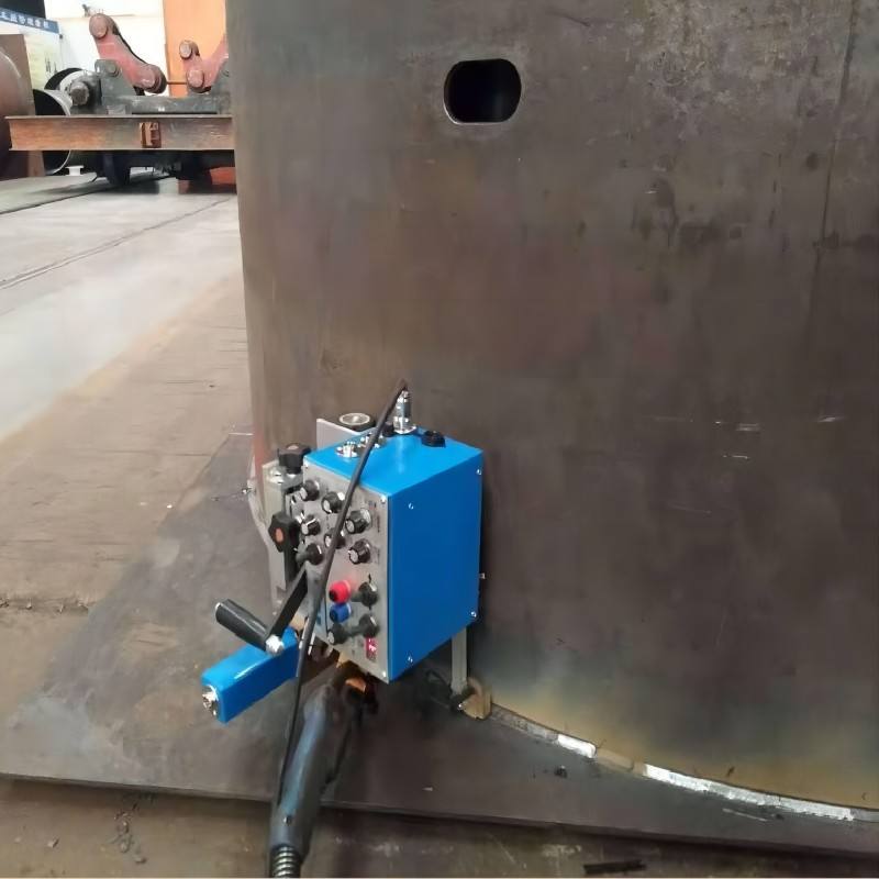
6.0 Automation Synergy: The Digital Workflow
The 20kW center functions as a cyber-physical system. The synergy between the power source and the automated material handling system is governed by a centralized CNC control that monitors over 200 data points per second.
6.1 Automatic Loading and Sensing
The “In-feed” system utilizes hydraulic lifters and lateral conveyors to stage beams. An automatic measuring station detects the exact length and cross-section of the incoming raw material. This data is fed back to the nesting engine; if a beam is 50mm shorter than the manifest, the software re-calculates the nest in real-time to avoid a “short-shot” cut.
6.2 Post-Process Identification
Following the 3D cut, an integrated fiber laser marking head applies alphanumeric strings or QR codes to each part. In offshore fabrication, traceability is a legal requirement. These marks link the physical part to its Mill Test Report (MTR) and Heat Number, ensuring that every brace and chord on the platform is fully traceable from the Jakarta shipyard back to the steel mill.
7.0 Conclusion: Technical Viability and ROI
The deployment of a 20kW 3D Structural Steel Processing Center with Zero-Waste Nesting represents a paradigm shift for Jakarta’s heavy industrial sector. The technical superiority of the 20kW source lies not just in its raw power, but in its ability to deliver high-precision, weld-ready components with minimal thermal distortion. When combined with the material savings afforded by zero-waste technology, the system addresses the two primary constraints of offshore fabrication: quality assurance and cost control. For the engineering teams tasked with building the next generation of energy infrastructure in the Java Sea, this technology is no longer an optional upgrade; it is the baseline for modern structural production.
Report End.
Ref: JKT-STR-20KW-001
Department: Structural Engineering & Laser Applications


