Cantilever Welding Robot Workstation
8-axis, teaching-free programming from a 3D model or a 3D scan
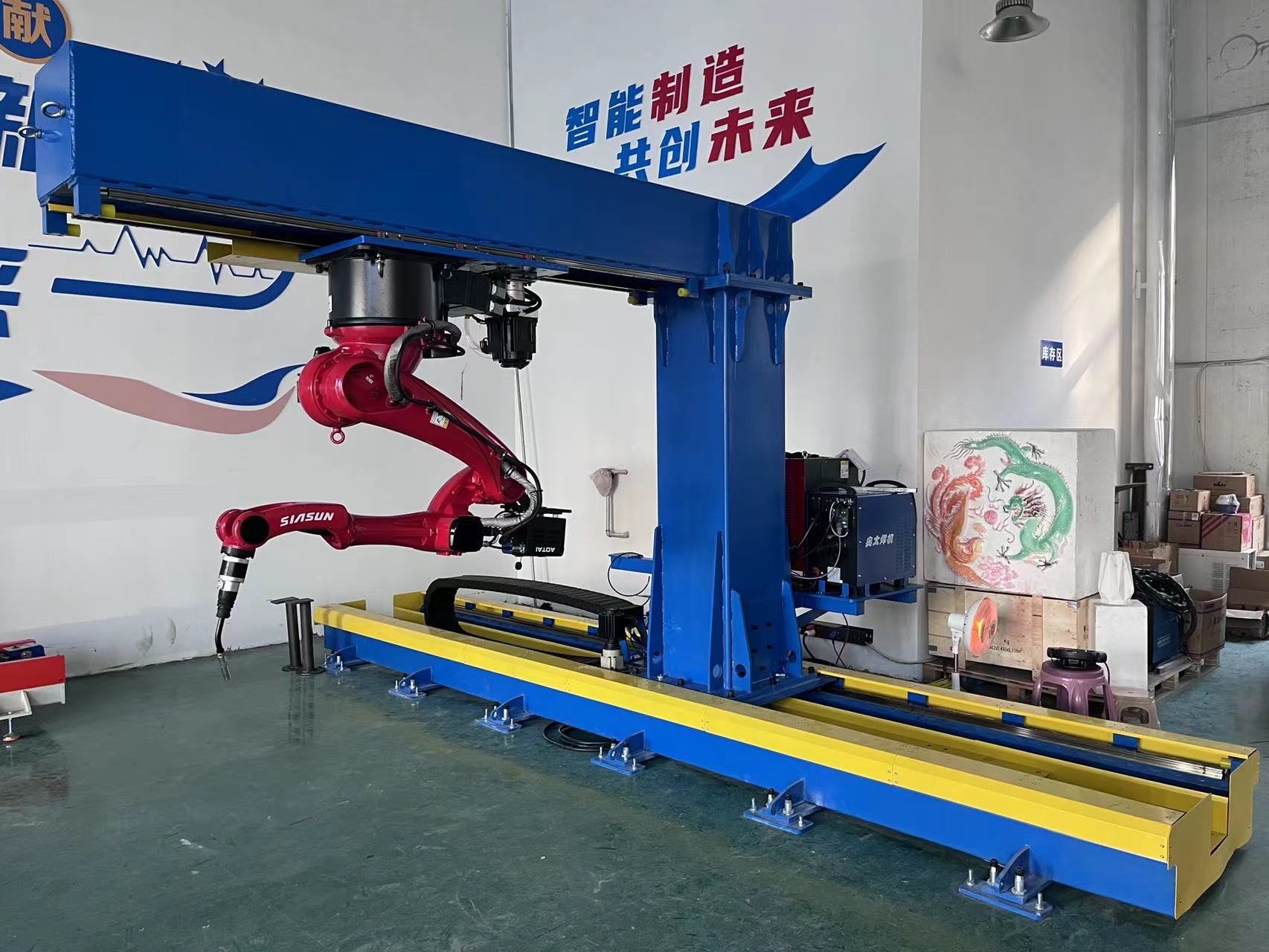
An 8-axis cantilever welding robot that programs itself. It takes the seams from your Tekla or 3D model, or scans the tacked part when there is no drawing, then plans, checks and welds the path. A steel structure welding robot for H-beam and box column welding, crane beams, roof beams and plate units up to 12.5 x 3.5 m.
- Axes
- 8 coordinated
- Max. part
- 12.5 x 3.5 x 0.5 m
- Seam camera
- 0.02 mm repeat.
- Welding
- 500 A, 100% duty
- Delivery
- ~20 working days
What is a teaching-free welding robot?
Also called a teachless or no-programming welding robot, it uses 3D vision and laser seam tracking instead of a teach pendant. A conventional welding robot only knows what an operator has taught it, point by point, with a teach pendant. On structural steel, where almost every beam is different, that teaching takes longer than the welding. A teaching-free station removes that step: the software reads the seams from a 3D model or a 3D scan, picks the welding parameters from a process database, plans a collision-free path and starts welding. The operator loads parts and checks the simulation.
| Programming method | Who programs | New part | Fit-up variation | Best for |
|---|---|---|---|---|
| Teach pendant | Trained robot programmer | Robot stops while every point is taught | Needs touch sensing or re-teaching | Large batches of one part |
| Drag teaching | Welder guides the arm by hand | Faster than pendant, still point by point | Limited | Small parts, cobots |
| Offline programming | Engineer at a PC | Path made at the PC, then calibrated on the part | Needs calibration | Repeat parts with good models |
| Teaching-free (this station) | Software, from model or scan | Scan or import, check, weld | Each seam measured by the 3D camera | One-off and mixed structural parts |
More background: teaching-free welding robots explained.
How teaching-free welding works: from a 3D model or a 3D scan
With a 3D model (STEP, IGS, IFC)
- Importthe part model; Tekla exports IFC
- Locatea laser line scan matches the model to the real part
- Planweld seam recognition, parameter matching and path planning
- Checkthe full path is tested for collisions
- Weldeach seam is measured by the camera, then welded
Without a drawing (scan-based)
- Scanthe global camera scans the tacked parts
- Rebuildthe part is reconstructed from the point cloud
- Planseams, parameters and path are generated
- Checkthe full path is tested for collisions
- Weldeach seam is measured by the camera, then welded
The 3D simulation (a digital twin of the cell) runs at 1:1 scale, so cycle time and collisions are known before the robot moves. For a seam in a tight corner, the operator can still teach a few points on the pendant and the robot welds it with the matched parameters.
How the 8-axis cantilever welding robot moves
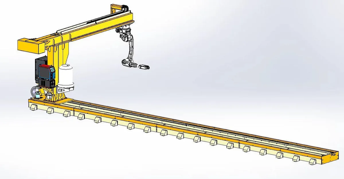
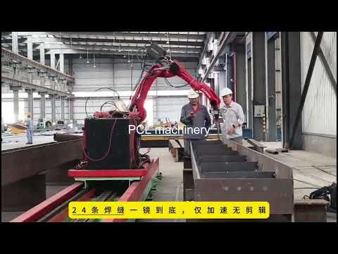
The 6-axis robot hangs from a cantilever arm. The arm travels along a 14 m floor track (X) and the robot moves along the arm (Y). With eight coordinated axes the robot reaches every seam on a 12.5 m part from above, and the open side of the station stays free for the crane.
Steel structure welding: H-beams, columns and crane beams
- H-section steel columns and box columns with brackets and stiffeners
- Roof beams, crane beams and gantry beams
- Corbels, purlin supports and connection plates
- Bridge internal diaphragms and stiffened plate units
Weld types: flat and vertical fillet welds, polyline fillet welds in one plane, wrap-around welds at plate ends, lap welds and curved welds in one plane.
Two geometry rules
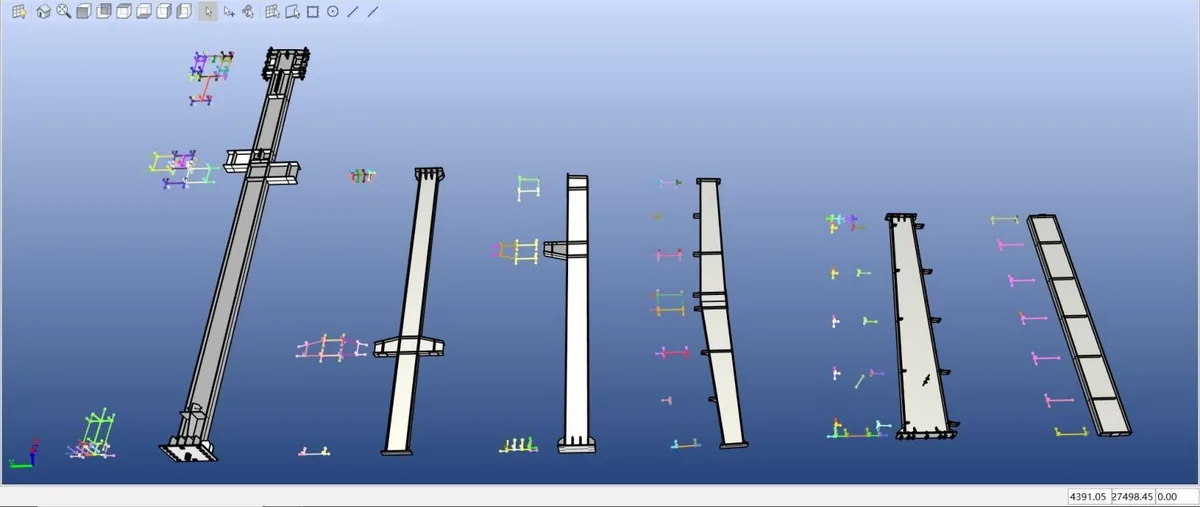
The camera and torch need room between plates. The software checks every seam and flags any it cannot reach.
Teaching-free welding robot specifications
Station
- Configuration
- Intelligent welding workstation, cantilever, 8 axes (6-axis robot + X track + Y arm)
- Max. workpiece (L x W x H)
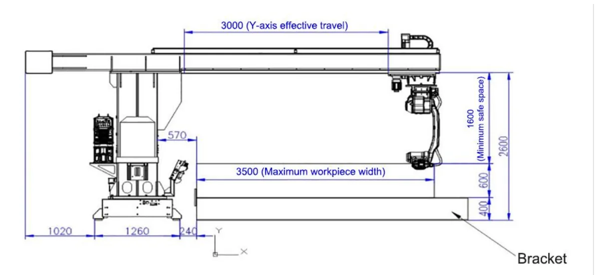
- 12,500 x 3,500 x 500 mm
- X track length
- 14,000 mm standard, longer on request
- Y travel
- 3,000 mm effective
- Travel speed X / Y
- up to 0.3 m/s
- Travel positioning accuracy
- ±0.5 mm, static and moving
- Arm load
- 500 kg
- Clearance under the arm
- 1,600 mm
- Footprint
- about 14,000 x 6,500 mm
- Servo drives
- X 3.14 kW, Y 2 kW
- Environment
- -10 to 45 °C, 20-80% RH, vibration ≤4.9 m/s²
- Delivery
- about 20 working days after advance payment
Welding robot
- Axes
- 6, vertical articulated
- Payload
- 6 kg
- Reach
- 2,014 mm
- Repeatability
- ±0.08 mm
- Max. speed, axes 1-3 / 6
- 189°/s / 974°/s
- Mounting
- floor or hanging
Main components
| Welding power source | Megmeet Dex2 500MPR: digital IGBT inverter, 500 A at 100% duty cycle, DC and pulse, 110 kHz switching |
|---|---|
| Welding torch | 550 A liquid-cooled robot torch, dual-channel gas shielding |
| Global scan camera | 2-4 m working distance, field of view up to 3,000 x 5,000 mm, 6,000 lines/s, IP65 |
| Seam camera | 3D line laser, 300-800 mm working distance, 0.02 mm repeatability at 300 mm, 480,000 lux ambient light tolerance, IP65 |
| Torch cleaning station | Automatic reaming and anti-spatter spray, about 4-5 s per cycle |
| Control | Industrial PC with teaching-free welding software; teach pendant; remote operation over TCP/IP |
| Options | Second robot on the same track, remote parameter adjustment during welding, MES link |
Robotic welding cell layouts
- Single station, 8-axis cantilever: the standard layout for long parts up to 3.5 m wide.
- Dual station (A/B): the robot welds on one side of the track while the other is unloaded and loaded, so the arc keeps running during crane work.
- Two robots on one track: two cantilevers weld one long part from both ends; the system keeps them from colliding.
- Ground rail, 7-axis: the robot travels on a floor track beside the part, for low buildings.
- Wider parts: above 3.5 m, use the gantry welding robot.
Welding process and weld quality
On long structural seams, weld quality depends on holding torch angle, stick-out and travel speed constant from the first metre to the last. In automated welding these stay fixed along a 12 m seam, so penetration, bead shape and heat input stay even.
3D scanning and seam tracking
Vision-guided welding works in two steps. A large-field 3D scan finds each part and builds a point cloud, then a 3D line laser camera on the torch measures every joint close up: position, gap and groove shape. This laser vision step is what makes weld seam recognition reliable on real, tacked parts. During welding, arc tracking (through-the-arc seam tracking) follows the joint as the plate heats and moves. Wire touch sensing is available as a backup on shiny or painted surfaces.
Penetration and fusion
Penetration depends on current, voltage, travel speed, torch angle and stick-out. The robot holds all five constant and the seam camera keeps the torch on the root, so lack of fusion at the root or toe is far less likely than with manual welding on long seams. Pulse MAG with mixed gas gives good side-wall fusion with little spatter; DC spray transfer gives the deepest penetration on thick fillet and groove welds.
Multi-layer, multi-pass welding
For large fillet welds and groove (bevel) welds, the software lays out the passes from the joint size: root pass, fill passes and cap pass, each with its own offset, weave and parameters. Arc tracking shifts each pass to the real joint. Complete joint penetration (CJP) and partial joint penetration (PJP) groove welds follow the groove preparation and backing in your procedure.
Wire and shielding gas
- Solid wire 1.0-1.6 mm, 1.2 mm most common (ER70S-6 / G3Si1 for carbon steel)
- Flux-cored wire 1.2-1.4 mm for higher deposition and positional welds
- Mixed gas 80% Ar / 20% CO2 (M21) for pulse and spray transfer with low spatter
- 100% CO2 for lower gas cost where spatter is acceptable
- Stainless steel with matching wire and Ar-rich gas
Heat input and distortion
Heat input (kJ/mm) = voltage x current x 60 / (travel speed in mm/min x 1000). Because the robot never changes speed or pauses mid-seam, heat input stays inside the procedure limits, and a fixed welding sequence repeats the same shrinkage on every beam. Preheat and interpass temperature still follow your WPS.
Standards and procedures
The robot welds to your welding procedure specification (WPS). Procedures can be qualified (PQR) to AWS D1.1, ISO 15614-1 and ship classification rules, and the station fits shops working under EN 1090 and ISO 3834. Every parameter set is stored in the database, so a qualified procedure is repeated exactly.
Typical MAG fillet weld parameters
Starting values for horizontal fillet welds, 1.2 mm solid wire, 80% Ar / 20% CO2. Final values come from your procedure qualification.
| Leg size | Passes | Current | Voltage | Travel speed |
|---|---|---|---|---|
| 6 mm | 1 | 260-300 A | 28-31 V | 40-55 cm/min |
| 8 mm | 1 with weave, or 2 | 280-320 A | 29-32 V | 30-45 cm/min |
| 10 mm | 3 | 280-320 A | 29-32 V | 35-50 cm/min per pass |
| 12 mm | 4-6 | 280-320 A | 29-32 V | 35-50 cm/min per pass |
Welding functions
- MIG/MAG welding, DC and pulse; carbon and stainless steel; solid and flux-cored wire
- Seven weave patterns: sine, triangle, arc, V, forward-back, reverse crescent and pendulum
- Wire touch sensing, laser positioning, laser scanning and laser seam tracking
- Arc tracking with multi-layer, multi-pass welding for thick plate
- Arc restart with path rollback after an interruption
- Stitch (intermittent) welding and fish-scale welding
- Remote adjustment of position, current, voltage and weave width during welding (optional)
- MES link: call up drawings by QR code, push welding data to production (optional)
What changes for a structural steel fabricator
| On a manual or taught-robot line | On the teaching-free station |
|---|---|
| Every new beam needs a robot programmer | The software programs from the model or the scan; the operator checks the simulation |
| Few experienced welders | Welding parameters come from the process database; one operator runs the station |
| Tack-up is never exactly as drawn | The seam camera measures each joint before welding and the path follows the real seam |
| Long beams mean walking, repositioning and restarts | The robot travels 14 m on the track; the part stays put |
| Robot idle while the crane loads | Dual-station layout: weld on A, load on B |
| Thick plate needs many passes | Arc tracking with multi-layer, multi-pass welding at 500 A, 100% duty cycle |
Teaching-free welding robot videos


Send a STEP model: what our engineering evaluation covers
For a new product, the assembly sequence decides how much of the welding a robot can do. Send the STEP model and your planned assembly and welding sequence. We run a robotic welding simulation of reachability and collisions, and where a different sequence raises the automation level, we propose it.
What the evaluation reports
- Robot accessibility and reachability for every seam
- Number and percentage of welds the robot can make, and the welds left for manual welding
- Welds made while the structure is still open, separated from the closing welds made after the deck or cover plate is fitted
- Dual-robot allocation, where two robots pay off
- Collision avoidance along every path
- Welding positions and workpiece handling, turning or repositioning
- Heat input, welding sequence and distortion control
- Fixtures and workpiece positioning needed
- Estimated cycle time and overall production efficiency
How we raise the robotic share
- Keep the structure open longer: weld bottom plates, internal frames, bulkheads and walls before the deck goes on, so most internal seams are reachable from above.
- Prefabricate separately: weld the deck or cover plate as its own sub-assembly on the same station.
- Leave only closing welds: the welds that can only be made after closing are listed separately, for robot or manual welding.
- Split long tracks: for very long parts, two units of about 13 m each keep travel accuracy and speed better than one 26 m track, and they can weld at the same time.
- Balance the heat: symmetric sequences and two robots welding opposite sides reduce distortion.
Typical products: pontoons and floating docks, ship blocks and double-bottom panels, bridge deck panels, box girders, columns and crane beams for serial production.
Welding robot ROI: estimate your payback
Enter the system price to see the payback period.
A simple estimate from labour savings only. Gains from faster throughput and less rework are not included.
Installation and service
What your shop provides
- About 14 x 6.5 m of level floor for the standard station
- Three-phase 380 V power (other voltages on request)
- Shielding gas and oil-free compressed air at 6 bar
- -10 to 45 °C, 20-80% humidity, no water, oil or flammable gas near the robot
- Crane access for loading and unloading
What we provide
- Layout drawing for your building and part range before you order
- Export packing and shipping
- On-site installation, commissioning and operator training (quoted per project)
- Remote support by WhatsApp, video and remote desktop, with replies within 24 hours
- Software updates and spare parts: contact tips, nozzles, liners
Other PCL welding systems
| System | Best for |
|---|---|
| Cantilever welding robot workstation (this page) | Long structural parts up to 3.5 m wide, one-off or mixed |
| Gantry welding robot | Wider and heavier parts: box girders, bridge and ship panels |
| Robotic welding station with positioner | Repeat batches of medium parts that need turning |
| AGV welding robot | Parts too large to move, such as tanks and hulls |
| Cobot welding machine | Small batches and short changeovers |
| H-beam production line | Assembling, submerged-arc welding and straightening built-up H-beams |
For a complete line, from cutting to welding, see cutting and welding solutions.
Frequently asked questions
What is a teaching-free welding robot?
A welding robot that writes its own program. Instead of an operator jogging the torch to each point with a teach pendant, the software takes the seams from a 3D model or from a 3D scan of the part, chooses welding parameters from a process database, plans the path, checks it for collisions and sends it to the robot.
Do I need 3D drawings?
No. With a STEP, IGS or IFC model (Tekla exports IFC) the software reads the seams from the model. Without a model, the global camera scans the tacked part, rebuilds it from the point cloud and finds the seams itself. Several parts on the station can be recognised in one scan.
How long does it take to program a new part?
The operator’s work is loading the part, starting the scan or selecting the model, and checking the path in the 3D simulation. There is no point-by-point teaching, so a new part does not stop production the way pendant teaching does. Cycle time and collisions are calculated in the simulation before the robot moves.
What is a cantilever welding robot workstation?
A welding cell in which an industrial welding robot hangs from a cantilever arm that travels along a floor track. The arm reaches over the part from one side, so the robot welds long structural parts from above while the other side stays open for crane loading. It costs less and needs less space than a gantry, and suits parts up to about 3.5 m wide.
What does 8-axis mean?
Six axes in the robot arm, plus two travel axes: X along the 14 m floor track and Y along the cantilever arm. All eight are coordinated, so the robot reaches every seam on a 12.5 m part without the part being moved.
What is the largest part it can weld?
12,500 x 3,500 x 500 mm (length x width x height) on the standard 14 m track. The track length sets the part length, so a longer track welds longer parts. For parts wider than 3.5 m, see the gantry welding robot.
How accurate is it?
The robot repeats to ±0.08 mm and the travel axes position to ±0.5 mm. What matters more for weld quality is that the 3D seam camera measures each joint before welding (0.02 mm repeatability at 300 mm), so the robot welds where the seam really is, not where the drawing says it should be.
Which welds can it make?
Flat and vertical fillet welds, polyline fillet welds in one plane, wrap-around welds at plate ends, lap welds and curved welds in one plane, on H-beam columns, roof beams, crane beams, corbels, purlin supports and bridge diaphragms. Thick joints get multi-layer, multi-pass welding with arc tracking.
Are there limits on part geometry?
The camera and torch need room. Keep stiffeners at least 200 mm apart (for stiffeners and flanges 200 mm high) and the angle between plates at 70 degrees or more. The software checks the space for each seam and flags any it cannot reach.
Can I still teach a weld by hand?
Yes. A teach pendant is included. For a seam in a tight corner, the operator teaches a few points and the robot welds it with the matched parameters from the database.
Which welding processes are supported?
Gas-shielded MIG/MAG welding in DC and pulse modes, with solid or flux-cored wire, on carbon steel and stainless steel. Seven weave patterns, stitch welding and fish-scale welding are included.
Can two robots work on one track?
Yes. Two cantilevers can share one track. The software and hardware keep them apart, so they can weld one long part from both ends or work on two stations while parts are loaded.
How long is delivery and what does the shop need?
About 20 working days after the advance payment for the standard station. The shop needs about 14 x 6.5 m of level floor, three-phase power, shielding gas and dry compressed air, and crane access for loading. The robot runs between -10 and 45 °C at 20-80% humidity.
How does the robot control weld penetration?
Penetration is set by current, voltage, travel speed, torch angle and stick-out. The robot keeps all five constant along the seam, and the 3D seam camera and arc tracking keep the torch on the joint root, so penetration stays even from one end of the beam to the other. For deeper penetration on thick joints, DC spray transfer and multi-pass welding are used.
Which wire and shielding gas should I use?
For carbon steel, 1.2 mm solid wire (ER70S-6 / G3Si1) with 80% Ar / 20% CO2 mixed gas is the usual choice: stable pulse and spray transfer with little spatter. 100% CO2 lowers gas cost but adds spatter. Flux-cored wire gives higher deposition. Stainless steel uses matching wire and Ar-rich gas.
Can it weld groove welds and full penetration joints?
Yes. Groove (bevel) welds are filled with multi-layer, multi-pass welding: root, fill and cap passes laid out from the joint size, with arc tracking correcting each pass. Complete and partial joint penetration welds follow the groove preparation and backing given in your welding procedure.
Can welds be qualified to AWS D1.1 or EN 1090?
The robot welds to your WPS. Procedures can be qualified to AWS D1.1, ISO 15614-1 or class society rules, and the station suits shops certified to EN 1090 and ISO 3834. Stored parameter sets mean a qualified procedure is repeated exactly.
How much does a robotic welding system cost?
The welding robot price depends on the layout and size (track or span length), the number of robots, the vision package, the welding power source brand and on-site service. Send your largest part size and production volume and we quote the exact configuration.
Can you evaluate my part from a STEP model?
Yes. Send the STEP model and, if you have one, your planned assembly and welding sequence. We simulate reachability and collisions, report how many welds the robot can make and which stay manual, separate open-structure welds from closing welds, and estimate cycle time. Where a different assembly sequence gives a higher robotic share or less distortion, we propose it.
Is a longer track always better?
No. Very long single tracks cost accuracy and speed. For parts around 26 m we usually recommend two units of about 13 m each: they hold accuracy better, can weld at the same time, and can also run as two separate stations.
Get a layout and quotation
Send your part data and we reply with a station layout, the right track length and a price.
- Largest part: length, width, height
- Plate thickness and weld types
- Parts per shift and building size
- Tekla or 3D models, if available