Kinematic Analysis and Application of Square Pipe Welding Robot
Square pipes occupy a significant proportion in the steel structure field, with T-joint connections being the most common type. Due to their special structure, the welding position is usually overhead welding, which is currently performed manually. However, the stability of joint quality is insufficient, and welding quality heavily depends on the experience of welding technicians. This results in long manufacturing cycles and high labor intensity.
With the rise of concepts such as Industry 4.0, intelligent manufacturing has become the trend in industrial development. Welding robots are becoming increasingly diverse, intelligent, and flexible. However, most welding robots are not easily movable and cannot perform uniform continuous welding. Therefore, developing intelligent equipment specifically for welding square pipe T-joints is of great significance for advancing China’s intelligent welding technology.
Robot kinematics is the foundation for motion control and trajectory planning. The commonly used Denavit-Hartenberg (D-H) modeling method is applied to establish the forward kinematics equations of robots, though solving these equations is often complex. The general solutions can be divided into two categories: numerical solutions and closed-form solutions. Tang Jian [1] used the D-H method to derive joint solutions for the ER10-C60 robot and analyzed the validity of multiple inverse kinematics solutions. Qian Yongheng [2] studied a desktop robot and obtained its numerical solutions.
For the newly developed four-degree-of-freedom robot, the D-H method was used to derive the kinematics equations and obtain numerical solutions. To address the low industrial automation level of square pipe T-joint welding, the study analyzed the welding robot’s kinematics based on the structural characteristics of square pipes. The reachability of the robot was verified, and trajectory planning was carried out in joint space to ensure the accuracy of the kinematic solutions. A prototype was built for welding experiments, verifying the feasibility and reliability of the welding equipment, providing theoretical support for future robot development and motion control.
1. Robot Design and Kinematic Analysis
1.1 Welding Robot Body Design
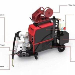
Based on the welding requirements for T-joints in steel structures, the robot needs to perform coordinated multi-axis motion with spatial straight lines and circular arcs to fit the welding trajectory. The robot must execute circumferential, axial, and radial movements around the square pipe, along with welding torch oscillation. This requires at least four degrees of freedom. Since some welding processes require real-time adjustments, an additional rotational degree of freedom is needed for torch control, enabling real-time adjustments to welding parameters and torch posture during welding.
Following the design principles of serial robots, a five-degree-of-freedom serial structure was chosen for the square pipe welding robot. Since square pipe workpieces are generally heavy, and considering the cost of fixtures and workholding methods, the robot is designed to clamp onto the workpiece using a rail system and move relative to the workpiece to complete the welding trajectory.
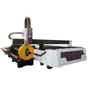
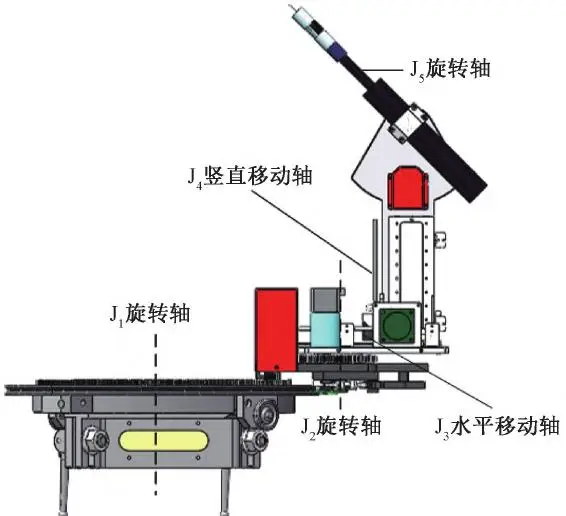
Based on this analysis, the robot structure is designed as shown in Figure 1. The J1, J2, and J5 axes are rotational, while the J3 and J4 axes are translational. J1, J2, J3, and J4 are used to fit the welding trajectory, while J5 is used to adjust the welding torch posture.
In practical engineering, the diameter of square pipe workpieces generally ranges from 80 to 150 mm. Considering spacer blocks (5–20 mm thick) and guide rail width, the designed workpiece rail diameter is set at 380 mm. The robot body can achieve ±365° rotation around the rail at a speed of 0–5 r/min, adjustable based on welding process requirements. The rotation range is 730°, and to prevent crater formation at the welding end, the movement continues for an additional 3–5 mm after arc extinction to avoid defects at the start and stop points.
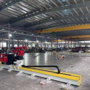
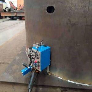
As shown in Figure 2, the circular rail system is designed to accommodate different sizes of square pipes by fixing spacer blocks of varying thicknesses (5–20 mm) on the inner side. These blocks allow for size adjustments based on different square pipe specifications while also increasing the static friction between the rail and pipe wall.
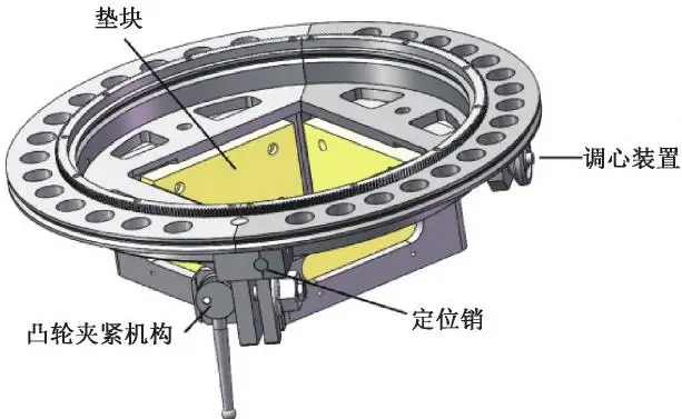
The inner and outer sides of the rail include guide tracks, and a self-centering device is designed on one side to ensure alignment between the rail center and the pipe center, minimizing workpiece positioning errors and reducing the impact of machining and manual clamping errors on welding quality.
Considering the working environment, fixture costs, and future maintenance, a cam-locking mechanism was selected for securing the rail system. This mechanism allows for quick installation and disassembly of the robot rail, reducing fixture setup time while improving work efficiency.