Pipe Bevel Types and Angles: 37.5°, 30°, J, X and K Bevels and How to Cut Them
By the PCL Group engineering team, Jinan · Updated 2026-10-28

Short answer
- The standard butt-weld pipe bevel is 37.5° ±2.5° with a 1.6 mm root face (ASME B16.25); line pipe often uses 30°.
- Walls over 22 mm use a compound bevel (37.5° then 10°), a J bevel or an X bevel to cut weld metal.
- A plasma torch at 37.5° cuts through about 1.26 times the wall, so size the cutter on the bevel length.
- Straight pipe ends can be bevelled by hand or by beveling machine; bevelled saddles and branch holes need 5-axis CNC.
In this article
- Why pipe ends are bevelled
- Bevel terms: angle, root face, root gap
- Pipe bevel types and standard angles
- How the bevel changes the amount of weld metal
- Bevels on branch joints and saddles
- How to bevel pipe: methods compared
- Plasma cutter pipe bevel: what to know
- Checking a pipe bevel
- Which machine for which bevel
Why pipe ends are bevelled
A square-cut pipe end can only be welded through its full thickness on thin walls. Once the wall is more than a few millimetres, the welder needs room to reach the root and build the joint up in layers. The bevel is that room: an angled face on each pipe end that forms a groove when the two ends meet. The geometry of the groove decides how easy the root pass is, how much weld metal goes in and how much the joint distorts.
Bevel terms: angle, root face, root gap
| Term | Meaning |
|---|---|
| Bevel angle | The angle of the bevelled face on one pipe end, measured from the plane square to the pipe axis (37.5° for example) |
| Included (groove) angle | The total angle of the groove when two bevelled ends meet: two 37.5° bevels give 75° |
| Root face (land) | The short flat left at the inside edge, so the root does not burn through; typically 1.6 mm |
| Root gap (root opening) | The gap between the two ends at the root, set by the welding procedure (WPS) |
| Hi-lo (mismatch) | Step between the inside surfaces of the two pipes; corrected by an internal taper or counterbore |
Pipe bevel types and standard angles
| Bevel | Typical geometry | Where it is used |
|---|---|---|
| V bevel, 37.5° | 37.5° ±2.5°, root face 1.6 ±0.8 mm (ASME B16.25), walls up to 22 mm | Process piping, fittings, flanges, general butt welds |
| V bevel, 30° | 30° +5°/−0°, root face 1.6 ±0.8 mm | Line pipe (API 5L) and pipelines welded to API 1104 |
| Compound bevel | 37.5° up to 19 mm, then 10° to the outside (ASME B16.25, walls over 22 mm) | Thick-wall piping, power and boiler pipe |
| J bevel | Small angle (often around 20°) with a radiused bottom of about 3 mm | Heavy wall where weld volume and heat input must be low |
| X bevel (double V) | V bevels from both sides around a central land | Very thick butt joints welded from both sides; large pipe and shells |
| K bevel | Double bevel on one member, square on the other | T-joints and branch connections welded from both sides |
| Square end | No bevel; sometimes a small gap | Thin walls, fillet-welded slip-on joints |
The welding procedure specification always has the final word: it sets the bevel, root face and gap for the process, position and material.
How the bevel changes the amount of weld metal
For a 25 mm wall with a 1.6 mm root face and a 2 mm root gap, the groove cross-section (without cap reinforcement) works out at:
| Bevel | Groove area per mm of weld length | Compared with 37.5° V |
|---|---|---|
| Single V, 37.5° | about 470 mm² | 100% |
| Single V, 30° | about 366 mm² | about 78% |
| X bevel, 37.5° each side | about 260 mm² | about 55% |
Less groove means less filler, fewer passes and less distortion, which is why compound, J and X bevels appear as walls get thicker. The trade-off is that narrower grooves are harder to reach and need more accurate preparation.
Bevels on branch joints and saddles
On a straight pipe end the bevel angle is the same all the way round. On a branch it is not. The angle between the branch wall and the main pipe surface changes around the joint, open at the sides and closed at the top and bottom. To keep the groove even, the bevel on the saddle has to change continuously, and the hole in the main pipe is bevelled to match. This is the joint that hand methods struggle with most, and the main reason fabricators cut branch connections on CNC pipe cutting and beveling machines. Our pipe saddle guide covers the layout.
How to bevel pipe: methods compared
| Method | Strengths | Limits |
|---|---|---|
| Angle grinder | Cheap, anywhere | Slow, operator-dependent angle and land |
| Portable pipe beveling machine (ID-clamp or split-frame) | Machined bevel and land, no heat-affected zone, compound and J profiles | Pipe ends only; slower on large, thick pipe |
| Oxy-fuel or plasma on a pipe bug | Fast straight bevels on site | Ends only; land and angle need checking |
| CNC plasma, 5-axis | Bevels on ends, saddles and branch holes in one pass with the profile | Workshop machine |
| CNC plasma and oxy-fuel | Same, plus very thick carbon steel walls | Oxy-fuel is slower and carbon steel only |
Plasma cutter pipe bevel: what to know
- Size the cutter on the bevel length. At 37.5° the torch cuts through the wall divided by cos 37.5°: a 20 mm wall becomes about 25 mm of cut, a 25 mm wall about 31.5 mm. At 30°, a 20 mm wall is about 23 mm.
- Edge angle. A plasma cut face is not perfectly square; one side of the kerf is closer to square than the other. Program the bevel direction so the good side lands on the part, and compensate the bevel offset on thick walls.
- Root face. Plasma cuts the bevel; the land is either left by a second square cut or set by the programmed torch path. Check it with a gauge on the first part.
- Edge condition. Air plasma on carbon steel can leave a thin nitrided layer that may cause porosity in some welding processes. For code work, many shops lightly grind the bevel face to bright metal before welding, or cut with oxygen plasma.
- Dross. Clean dross from the inside edge before fit-up; it gets in the way of the root.
On PCL CNC pipe cutters the bevel head tilts continuously from 0 to ±45°, with up to ±60° available for special weld preparations, and parts can be imported from Tekla or AutoCAD. The video shows a 5-axis machine cutting and bevelling pipe in one pass:

Above about 40 mm of carbon steel, oxy-fuel takes over. Machines that carry both, such as our 5-axis plasma and oxy-fuel pipe bevel cutting machine, bevel walls up to 200 mm.
Checking a pipe bevel
- Angle: bevel protractor or a welding gauge; 37.5° ±2.5° for B16.25 ends.
- Root face: 1.6 ±0.8 mm all round, measured at several points.
- Squareness: the end square to the pipe axis, checked with a pipe square or wrap.
- Cleanliness: no dross, scale, paint or oil within about 25 mm of the bevel.
- Fit-up: root gap and hi-lo within the welding procedure.
Which machine for which bevel
| Your work | Machine |
|---|---|
| V bevels on ends, saddles and branch holes, pipe to Ø600 mm, plus square tube | 5-axis tube plasma cutting machine |
| Thick-wall round pipe, plasma and oxy-fuel bevels to 200 mm | 5-axis plasma and oxy-fuel pipe bevel cutter |
| Bevelled headers and branches, Ø200-1500 mm | Roller-bed CNC plasma pipe cutting machine |
| V, X and K bevels on Ø600-2000 mm pipe | 6-axis large diameter pipe cutter |
Have a pipe job in mind? Send the pipe size, wall and joint, and an engineer will tell you which method or machine fits.
Ask on WhatsAppMachines mentioned in this article
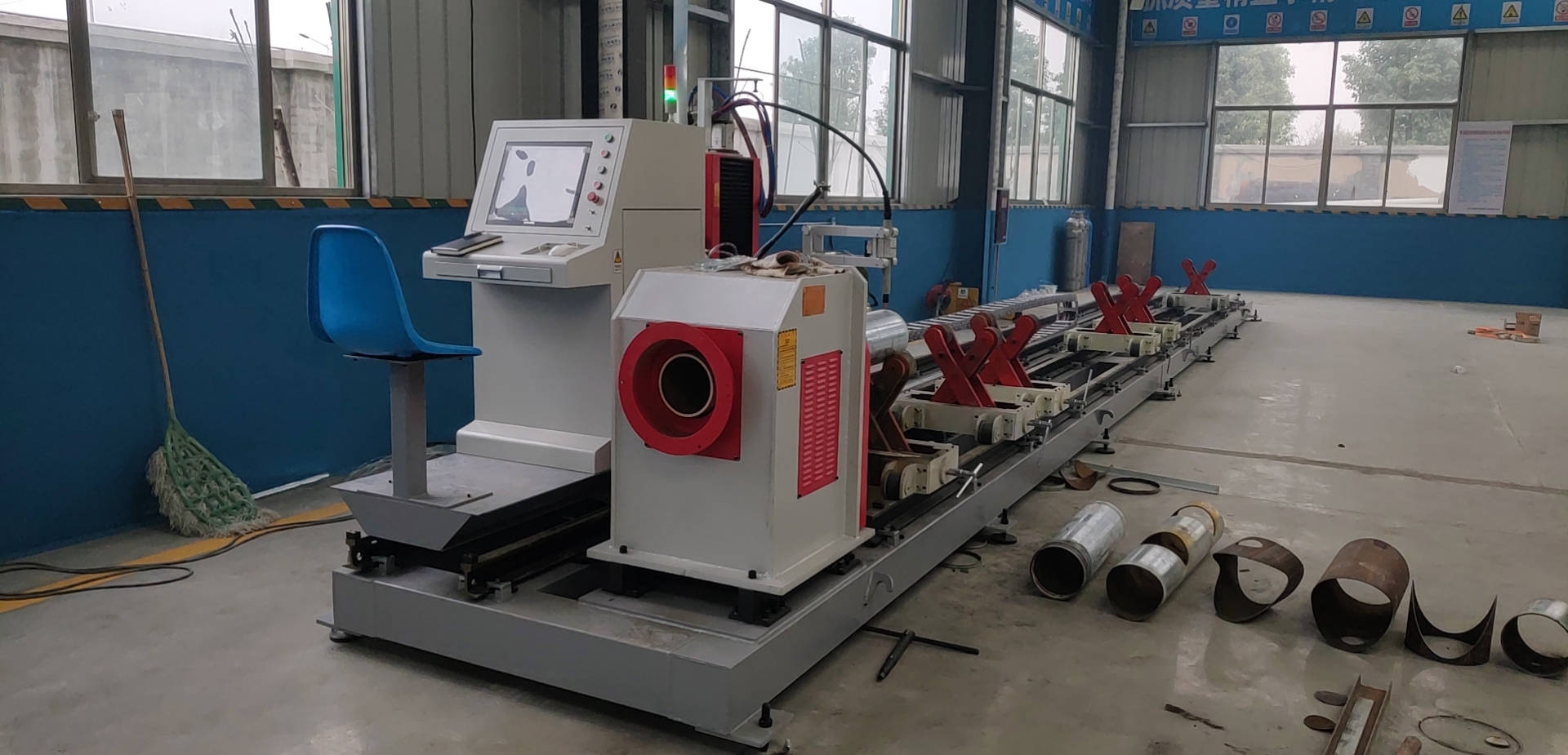
5-Axis Plasma and Oxy-Fuel Pipe Bevel Cutter
Bevels to 200 mm wall, Ø40-600 mm.
Compare all models →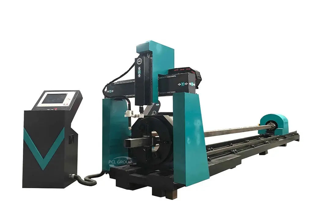
5-Axis CNC Tube Plasma Cutting Machine
Bevelled saddles, holes and ends.
View machine →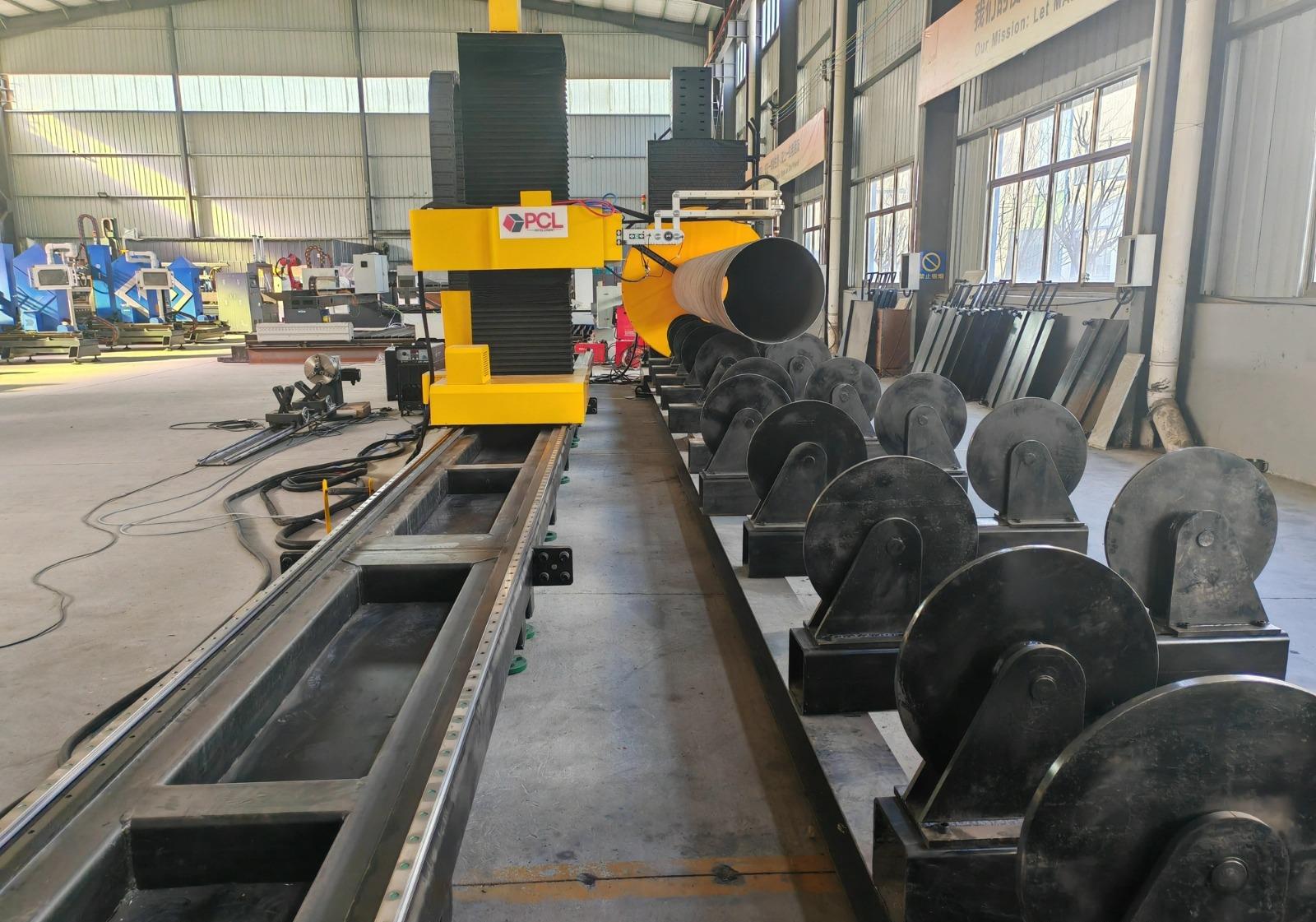
6-Axis Large Diameter Pipe Cutter
V, X and K bevels to Ø2000 mm.
View machine →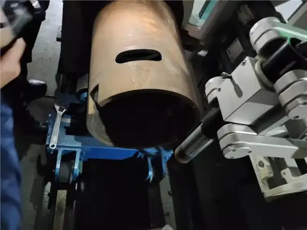
CNC Pipe Cutting and Beveling Machines
All pipe cutting models compared.
View machine →FAQ
What is the standard bevel angle for pipe welding?
37.5 degrees plus or minus 2.5 degrees with a 1.6 mm root face, per ASME B16.25, for walls up to 22 mm. Line pipe to API 5L is often bevelled at 30 degrees.
Why is a pipe bevel 37.5 degrees?
Two 37.5 degree ends make a 75 degree groove, wide enough for good access to the root while keeping the weld volume reasonable on common wall thicknesses.
What is a compound bevel?
For walls over 22 mm, ASME B16.25 uses 37.5 degrees up to 19 mm and 10 degrees above, which reduces weld metal compared with a single 37.5 degree bevel through the full wall.
What is the root face on a pipe bevel?
The small flat at the inside edge of the bevel, typically 1.6 mm plus or minus 0.8 mm. It supports the root pass and stops burn-through.
What is the difference between a J bevel and a V bevel?
A J bevel has a small angle and a radiused bottom, so the groove stays narrow; it uses less weld metal than a V bevel on thick walls but needs machining or very accurate cutting.
What are X and K bevels?
An X bevel is a double V on a butt joint welded from both sides. A K bevel is a double bevel on one member of a T or branch joint.
Can you bevel pipe with a plasma cutter?
Yes, by tilting the torch to the bevel angle. Size the plasma for the bevel length, which is about 1.26 times the wall at 37.5 degrees, and check the root face.
Should you grind a plasma-cut bevel before welding?
For code welding many shops lightly grind the face to bright metal, because air plasma can leave a nitrided layer that may cause porosity. Follow your welding procedure.
How do you bevel a saddle or branch hole?
The bevel angle has to change around the joint. By hand it is ground; on a 5-axis CNC pipe cutter the torch tilts continuously as it cuts.
Plasma or oxy-fuel for bevelling thick pipe?
Plasma is faster up to about 40 mm of carbon steel. Oxy-fuel bevels thicker carbon steel, up to 200 mm on dual-torch machines.