Field Technical Report: Implementation of 20kW 3D Structural Steel Processing in Houston Mining Machinery Fabrication
1. Executive Summary and Site Context
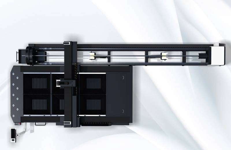
This report details the technical deployment and operational assessment of a 20kW 3D Structural Steel Processing Center equipped with ±45° bevel cutting capabilities. The subject site is a heavy-duty mining machinery fabrication facility located in the Houston industrial corridor. The primary objective was to replace legacy plasma cutting and manual mechanical beveling processes with high-power fiber laser technology to improve the structural integrity and assembly throughput of mining equipment frames, specifically vibratory screens, heavy-duty conveyors, and underground support structures.
The Houston region’s reliance on A572 Grade 50 and other high-strength low-alloy (HSLA) steels necessitates a cutting solution that minimizes the Heat Affected Zone (HAZ) while maintaining high precision over large-format structural profiles (H-beams, I-beams, and C-channels).
2. The Synergy of 20kW Fiber Laser Sources in Heavy Gauged Steel
The transition to a 20kW fiber laser source represents a critical shift in power density. In the context of structural steel used in mining—often exceeding 25mm in flange thickness—lower wattage lasers (6kW–12kW) struggle with piercing speeds and edge quality.
The 20kW source provides a significant surplus of energy, allowing for high-speed melt-blowing through thick sections. At this power level, the laser maintains a stable keyhole even when executing complex 3D maneuvers. The high photon density results in a narrower kerf width compared to plasma, which is vital for the interlocking joints required in mining machinery frames. Furthermore, the 20kW output facilitates the use of oxygen-assisted cutting for thick carbon steel with a surface finish that often bypasses the need for secondary shot blasting or grinding.
3. Kinematics of ±45° 3D Bevel Cutting
The core technological differentiator of this processing center is the 5-axis 3D cutting head. Traditional 2D laser systems are restricted to perpendicular cuts, leaving the “weld preparation” or beveling to manual operators or secondary milling machines.
Mechanism of the Bevel Head:
The processing center utilizes a specialized cutting head with high-dynamic B and C axes. This allows the laser nozzle to tilt up to ±45° relative to the material surface. In structural steel processing, this capability is not merely for aesthetics but for functional weld geometry.
* V-Type, Y-Type, and K-Type Preparations: The system can execute these bevels directly on the beam flanges and webs in a single pass.
* Constant Focal Length Maintenance: The 3D head incorporates high-speed capacitive sensing to maintain a constant standoff distance even at extreme angles. This is critical in Houston’s mining sector, where beams often exhibit slight “bowing” or “twisting” due to manufacturing tolerances in the steel mill.
4. Solving Precision and Efficiency Issues in Mining Machinery
Mining machinery is subjected to extreme cyclic loading and vibration. Consequently, the weld quality of the primary structural chassis is paramount.
The Problem of Manual Beveling:
Previously, the facility utilized manual plasma gouging or track-burners to create bevels. This introduced significant human error, inconsistent root faces, and an oversized HAZ. These inconsistencies led to excessive weld filler usage and increased the risk of fatigue failure at the joint.
The Laser Solution:
With the ±45° 3D laser, the “Fit-up” tolerance is reduced from ±3.0mm (plasma/manual) to ±0.2mm. By achieving a precise K-butt or V-butt joint directly from the laser center, the welding robots can operate with high-speed, synchronized parameters, reducing the “arc-on” time by approximately 40%. The precision of the 3D cut ensures that the stress distribution across the mining equipment frame is uniform, directly extending the service life of the machinery in the field.
5. Automated Structural Processing: Integration and Workflow
The processing center is not merely a cutting tool but a fully automated structural line. In the Houston facility, the system handles beams up to 12 meters in length.
Loading and Material Centering:
Structural steel is notoriously irregular. The system utilizes a four-chuck (or multi-chuck) design to provide continuous support and rotation. Automatic laser scanning profiles the actual dimensions of the loaded H-beam, comparing it against the CAD model. The software then compensates for any dimensional deviations (web eccentricity or flange tilt) in real-time before the 20kW head begins the piercing sequence.
Common Line Cutting and Nesting:
By utilizing 3D nesting software, the system optimizes the layout of parts across the beam length. This reduces “scrap-end” waste, a significant cost factor when dealing with the heavy-section beams typical of the mining industry.
6. Software and CAD/CAM Synchronicity
The complexity of 3D beveling on structural shapes requires advanced software integration. The Houston deployment utilizes a direct “Tekla-to-Machine” workflow.
1. Import: 3D models of mining structures (typically .stp or .ifc files) are imported.
2. Automatic Feature Recognition: The software identifies holes, slots, and beveled edges on different planes of the beam.
3. Path Optimization: The algorithm determines the most efficient sequence to prevent thermal distortion. For 20kW cutting, the “heat management” path is vital; the software ensures that the laser doesn’t dwell too long in one zone, preserving the structural metallurgy of the Grade 50 steel.
7. Operational Impact on the Houston Mining Sector
The implementation of this technology addresses several regional challenges:
* Labor Shortages: By automating the beveling process, the facility reduced its reliance on highly skilled manual grinders and layout personnel.
* Throughput: A processing task that previously took 8 hours (layout, cut, move, bevel, clean) is now completed in 45 minutes of machine time.
* Quality Assurance: The 3D laser provides digital traceability. Every cut, hole, and bevel is logged, ensuring that the mining machinery meets MSHA (Mine Safety and Health Administration) structural standards.
8. Technical Challenges and Mitigation Strategies
During the field commissioning, two primary technical challenges were identified:
1. Back-Wall Reflection: When cutting the top flange of an H-beam with 20kW of power, the “blow-through” can damage the bottom flange or the machine’s internal components.
* Mitigation: The system uses a “copper-slat” protective bed and intelligent beam-shuttering that modulates power based on the detection of the underlying material layer.
2. Dross Adhesion on Extreme Bevels: At 45°, the effective thickness of the material increases by approximately 1.4x.
* Mitigation: Optimized gas dynamics. We implemented a high-pressure nitrogen/oxygen mixing station that allows for a “cleaner” blow-out of the molten pool during steep-angle cuts, ensuring the bevel face remains weld-ready without secondary cleaning.
9. Conclusion
The deployment of the 20kW 3D Structural Steel Processing Center in Houston has redefined the production benchmarks for mining machinery fabrication. The integration of high-power fiber laser sources with ±45° beveling kinematics addresses the core pain points of heavy steel processing: precision, weld preparation, and labor intensity. As the industry moves toward more complex, fatigue-resistant designs, the ability to process structural profiles with sub-millimeter accuracy and integrated weld-geometry will be the defining standard for structural steel excellence.
End of Report.
Author: Senior Lead Engineer, Laser Systems & Structural Metallurgy.


