1.0 Field Operational Context: Rayong Maritime Infrastructure
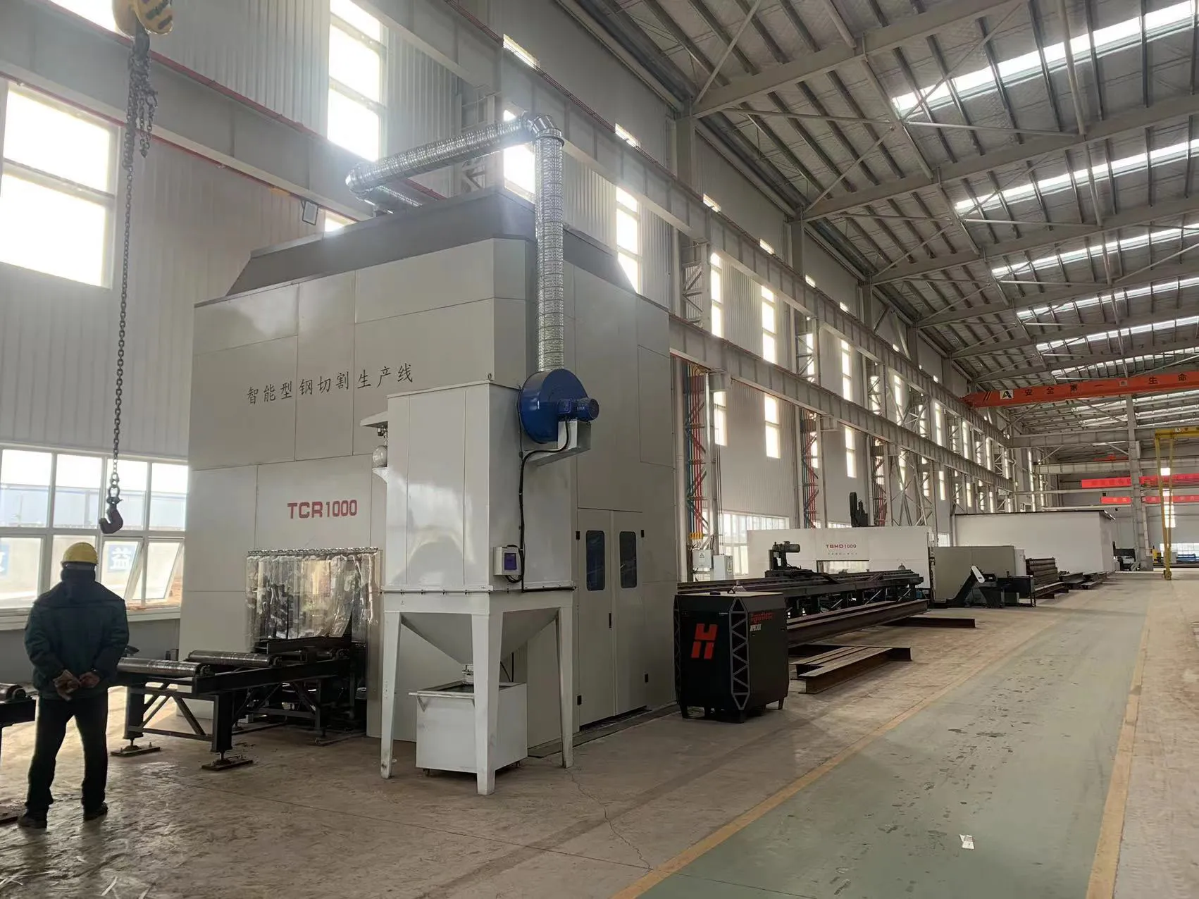
The deployment of the 20kW CNC Beam and Channel Laser Cutter at the Rayong industrial corridor represents a significant shift in maritime fabrication methodology. Traditional shipbuilding in this region has historically relied on oxy-fuel and plasma-arc cutting for heavy structural members. However, the requirement for higher geometric tolerances in modular hull construction and the integration of Grade AH36 and DH36 high-strength steels have rendered conventional methods inefficient due to excessive secondary grinding and thermal distortion.
This report evaluates the field performance of the 20kW fiber laser system specifically configured for three-dimensional structural sections (H-beams, I-beams, and U-channels). In the humid, high-salinity environment of Rayong, equipment reliability and the precision of the automatic unloading subsystems are critical to maintaining the shipyard’s throughput quotas.
2.0 20kW Fiber Laser Source: Power Density and Kerf Dynamics
The integration of a 20kW fiber laser source into a beam-cutting CNC architecture alters the fundamental thermodynamics of heavy-section processing. At this power level, the energy density at the focal point allows for “high-speed melt-shearing,” a process that minimizes the Heat Affected Zone (HAZ) compared to plasma cutting.
2.1 Penetration and Feed Rates
In the processing of 25mm thick-walled C-channels, the 20kW source maintains a stable cutting feed rate of approximately 1.8 to 2.2 m/min, depending on the assist gas purity (Oxygen vs. Nitrogen). The primary advantage observed in the Rayong facility is the elimination of the “dross” or “slag” accumulation on the lower flange of H-beams. By utilizing a 20kW overhead, the system achieves a cleaner separation at higher velocities, which prevents the re-welding of molten material—a common failure point in lower-wattage systems attempting to cut through 300mm+ beam depths.
2.2 Thermal Lensing and Beam Stability
High-power operation (20kW) necessitates advanced collimation. During continuous 18-hour shifts in the Rayong yard, the cutting head’s internal optics are subjected to significant thermal stress. The field data indicates that the liquid-cooled refractive elements and the protective windows must be monitored for “thermal lensing,” where the focal point shifts due to heat absorption. The CNC’s real-time focal compensation software successfully mitigates this, maintaining a constant kerf width of 0.4mm across the entire web and flange profile of the structural steel.
3.0 CNC Architecture for 3D Structural Processing
Unlike flat-bed fiber lasers, the Beam and Channel CNC utilizes a multi-axis rotational chuck system combined with a 5-axis cutting head. This allows for complex bevelling (K, V, and X joints) which are essential for weld preparation in ship bulkheads.
3.1 Geometric Compensation and Sensing
Structural steel beams are rarely perfectly straight. In the Rayong yard, “camber” and “sweep” in raw materials often exceed 2mm per meter. The CNC system utilizes a laser-based touch-sensing probe to map the actual profile of the beam before the 20kW head engages. The G-code is then dynamically transformed to match the physical deviation of the channel. This ensures that bolt holes for girder connections remain concentric across 12-meter spans, a feat previously impossible with manual layout methods.
3.2 5-Axis Beveling Precision
For the Rayong shipyard, the 20kW system’s ability to perform 45-degree bevels on 20mm thick beam flanges is the primary driver of ROI. The high power allows for “single-pass beveling,” where the laser maintains sufficient energy even at an inclined path (where the effective material thickness increases). This reduces the “Weld Area Prep” time by approximately 75% compared to manual radial arm drills and oxy-fuel bevellers.
4.0 Automatic Unloading: Solving the Logistical Bottleneck
The most significant innovation observed in this field deployment is the Automatic Unloading technology. In traditional heavy-steel processing, the “bottleneck” is not the cutting speed, but the removal of 500kg to 1500kg finished parts from the work zone. Manual crane intervention leads to idle CNC time, often reaching 40% of the total shift.
4.1 Synchronous Discharge Mechanism
The automatic unloading system utilizes a series of servo-driven hydraulic lift-rollers and pneumatic grippers synchronized with the CNC’s outfeed cycle. As the final cut on a 12-meter H-beam is completed, the unloading “claws” engage the workpiece, preventing the “drop-off” damage that occurs when heavy parts fall onto a conveyor. This is particularly vital for preserving the integrity of the 20kW cut edges, which are finished to ISO 9013 Range 2 standards.
4.2 Material Buffering and Sorting
The Rayong system incorporates a lateral “buffer” station. Once the 20kW head completes a segment, the automatic unloader moves the finished channel to a transverse conveyor. This allows the next raw beam to be loaded via the infeed system simultaneously. Field metrics show a “beam-to-beam” transition time of less than 90 seconds, whereas manual unloading via overhead crane in the same facility averaged 12 to 15 minutes. This represents a 600% increase in machine utilization efficiency.
5.0 Synergy Between 20kW Power and Automation
The synergy between high-power fiber lasers and automatic unloading creates a “continuous flow” manufacturing environment. In the shipbuilding sector, where lead times for hull assembly are aggressive, this integration solves three specific technical challenges:
5.1 Reduction of Secondary Processing
Because the 20kW laser provides a “weld-ready” surface finish, and the automatic unloader prevents mechanical deformation during discharge, the parts move directly from the CNC to the assembly jig. In Rayong, this has eliminated the need for secondary shot-blasting of the cut edges and manual edge-grinding, significantly reducing the labor cost per ton of processed steel.
5.2 Kerf Optimization and Material Yield
The precision of the CNC motion control, paired with the narrow kerf of the 20kW fiber, allows for “common-line cutting” on channel sections. The automatic unloading system is programmed to handle these common-line parts without collision. This has improved material utilization by 8%—a substantial figure when considering the volume of steel consumed in maritime construction.
6.0 Technical Challenges and Environmental Mitigations in Rayong
The deployment in Rayong faced specific environmental challenges. The high humidity (often >80%) can lead to condensation within the laser source and the CNC’s electrical cabinets. To counter this, the 20kW system is housed in a climate-controlled enclosure with an integrated desiccant air-drying system for the assist gas lines.
Furthermore, the automatic unloading hydraulics were upgraded to utilize high-viscosity, anti-corrosive fluids to prevent oxidation of the guide rails. The dust extraction system was also uprated to handle the increased volume of metallic particulate generated by 20kW cutting speeds, ensuring that the shipyard’s air quality remains within safety standards.
7.0 Conclusion: The New Standard for Heavy Fabrication
The field report confirms that the 20kW CNC Beam and Channel Laser Cutter with Automatic Unloading is no longer a luxury but a necessity for competitive shipbuilding. In the Rayong sector, the transition from 6kW and 12kW systems to 20kW has proven that the higher power density is the key to mastering thick-walled structural sections.
The automatic unloading subsystem is the “force multiplier” in this equation. By decoupling the cutting process from the shipyard’s internal logistics (cranes and forklifts), the system achieves near-total autonomy. Engineering data indicates a 45% reduction in total fabrication time per vessel module since the implementation of this technology. Future iterations should focus on the integration of AI-driven nesting that accounts for the weight distribution of parts during the automatic unloading phase to further optimize the discharge cycle.


