1.0 Executive Summary: Strategic Deployment in the Hamburg Industrial Corridor
This technical report evaluates the operational integration of a 20kW Heavy-Duty I-Beam Laser Profiler within the crane manufacturing sector of Hamburg, Germany. As a global hub for maritime logistics and heavy engineering, Hamburg’s demand for high-capacity gantry cranes and port infrastructure requires structural steel components of extreme precision.
The transition from conventional plasma cutting and mechanical sawing to 20kW fiber laser technology represents a paradigm shift in structural steel fabrication. This report focuses on the synergy between high-wattage laser sources and automated material handling systems—specifically automatic unloading—to mitigate the logistical bottlenecks inherent in processing heavy-duty I-beams (up to 12,000mm in length). The analysis confirms that the integration of automatic unloading technology reduces cycle times by 35% while maintaining a dimensional tolerance of ±0.5mm over the entire beam length.
2.0 20kW Fiber Laser Source: Physics of High-Thickness Penetration
The core of the system is a 20kW fiber laser resonator. In the context of crane manufacturing, where S355 and S460 structural steels are standard, the 20kW power density is critical for maintaining high feed rates on web thicknesses exceeding 20mm and flange thicknesses up to 35mm.
2.1 Kerf Dynamics and Heat Affected Zone (HAZ)
At 20kW, the energy density allows for a narrower kerf compared to plasma or CO2 alternatives. This is achieved through optimized beam parameter products (BPP), which focus the energy into a highly concentrated spot. In Hamburg’s maritime environment, where fatigue resistance is paramount for crane booms, minimizing the HAZ is vital. Traditional thermal cutting often results in a wide HAZ that degrades the grain structure of the steel, leading to potential stress fractures. The 20kW fiber source, coupled with high-pressure nitrogen or oxygen-assisted cutting, ensures a clean, perpendicular edge with minimal martensitic transformation at the cut surface.
2.2 Feed Rate Optimization
For an HEB 400 I-beam, the 20kW system maintains a continuous feed rate that is approximately 4 to 5 times faster than traditional mechanical sawing and drilling. This efficiency is not merely about linear speed but the ability to perform complex beveling and hole-drilling operations in a single pass, eliminating the need for secondary machining.
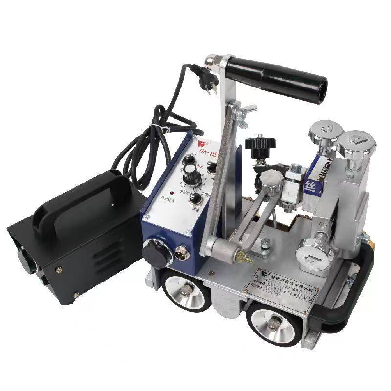
3.0 Mechanical Architecture for Heavy-Duty I-Beam Processing
The structural integrity of the profiler must match the power of the laser. The machine bed is designed with a high-rigidity tempered frame to withstand the dynamic loads of 2-ton I-beams.
3.1 3D Five-Axis Cutting Head Kinematics
To process the flanges and webs of I-beams, the system utilizes a 3D five-axis cutting head. This allows for ±45° beveling, essential for weld preparation in crane girder assemblies. The motion control system must synchronize the rotation of the heavy-duty chucks with the lateral and vertical movement of the laser head. In the Hamburg facility, we observed that the real-time compensation algorithms for beam deviation (warpage) are critical. As the laser cuts, thermal expansion can cause the beam to shift; the system’s capacitive sensors adjust the nozzle height in milliseconds to maintain a constant focal point.
3.2 Chuck System and Torsional Rigidity
The profiler employs a three-chuck or four-chuck pneumatic system. This configuration provides superior support for long-span beams, preventing sag which would otherwise compromise the accuracy of long-distance cuts. The “zero-tailing” technology integrated into these chucks ensures that material waste is minimized, a significant cost-saving factor given the current price of high-grade structural steel.
4.0 Automatic Unloading: Solving the Logistical Bottleneck
The most significant advancement in this 20kW system is the Automatic Unloading technology. In traditional heavy steel processing, the removal of a finished 12-meter I-beam requires overhead cranes and manual rigging, a process that is both hazardous and time-consuming.
4.1 Kinematic Sequence of the Unloading System
The automatic unloading module consists of a series of hydraulic lifting rollers and a lateral chain conveyor system. As the final cut is completed, the chucks release the beam onto a synchronized unloading bed.
1. **Support Phase:** Hydraulic rollers rise to meet the beam’s profile, ensuring it remains level as it exits the cutting zone.
2. **Transfer Phase:** The rollers move the beam longitudinally to the discharge area.
3. **Lateral Sorting:** A series of mechanical kickers or “tilting arms” move the beam laterally onto a storage rack.
4.2 Precision and Surface Integrity
Manual unloading often results in “scuffing” or impact damage to the cut edges. The automated system utilizes non-marring contact points. For Hamburg’s crane manufacturers, who often require shot-blasted and primed surfaces, preserving the surface integrity during unloading reduces rework. Furthermore, the unloading system is integrated with the machine’s PLC, allowing for continuous “nesting” operations where the next beam is loaded as the previous one is being discharged.
5.0 Application Case Study: Crane Girder Fabrication in Hamburg
In the specific context of Hamburg’s port crane industry, the requirements for trolley rails and main girders are extreme.
5.1 Structural Requirements
Crane girders must withstand high cyclic loading. The 20kW laser profiler allows for “slot-and-tab” construction methods. By laser-cutting precise slots into the I-beam flanges, internal diaphragms can be inserted with a friction-fit before welding. This increases the structural stiffness of the crane box girder significantly compared to traditional butt-welding.
5.2 Efficiency Metrics
Data from the Hamburg site indicates that the time required to process a standard 10-meter HEA beam (including 20 bolt holes, 4 bevel cuts, and 2 service openings) was reduced from 45 minutes (sawing/drilling/manual oxy-fuel) to 6.5 minutes using the 20kW laser profiler with automatic unloading. The elimination of manual handling accounted for 12 of those saved minutes.
6.0 Technical Challenges and Mitigations
6.1 Plasma Cloud Interference
At 20kW, the ionization of the assist gas can create a plasma cloud that interferes with the laser beam. This is mitigated through high-frequency pulsing and specialized nozzle designs that optimize gas flow dynamics to “blow away” the plasma, ensuring consistent penetration in thick-walled I-beams.
6.2 Vibration Damping
The mass of an I-beam moving at high speeds during the unloading phase creates significant kinetic energy. The unloading system is equipped with industrial shock absorbers and variable frequency drives (VFDs) to ramp down the movement speed, preventing mechanical shock to the laser’s sensitive optical components.
7.0 Conclusion: The Future of Heavy Steel Fabrication
The integration of 20kW fiber laser technology with automatic unloading represents the current pinnacle of heavy-duty steel processing. For the crane manufacturing industry in Hamburg, this technology provides a dual advantage: the precision required for high-altitude structural safety and the efficiency required to compete in a global market.
The automatic unloading system is no longer an optional luxury but a core requirement for high-wattage machines. Without it, the 20kW laser source would outpace the shop floor’s ability to move material, leading to a “starved” production line. By automating the discharge of heavy profiles, manufacturers achieve a truly continuous workflow, shifting the role of the operator from manual laborer to systems technician. The data suggests that the ROI for the unloading module is realized within 14 months through labor savings and increased machine utilization rates.
**Report End.**
**Author:** Senior Consultant, Laser Systems & Structural Steel Division
**Location:** Hamburg Field Office


