Technical Field Report: 6000W Heavy-Duty I-Beam Laser Profiler Deployment
1. Executive Summary: The Structural Shift in Houston’s Railway Infrastructure
In the industrial corridors of Houston, Texas—a primary nexus for Class I freight railroads including Union Pacific and BNSF—the demand for rapid, high-precision structural steel fabrication has reached a critical inflection point. Traditional methods of processing heavy-duty I-beams, such as plasma cutting and mechanical drilling, are increasingly seen as bottlenecks due to secondary finishing requirements and significant tolerance stack-up. This report analyzes the field performance of the 6000W Heavy-Duty I-Beam Laser Profiler, specifically examining the integration of automatic unloading technology and its impact on the fabrication of railway bridge components, support pylons, and freight terminal infrastructure.
2. Power Dynamics: The 6000W Fiber Laser Source
The selection of a 6000W fiber laser source is a calculated engineering decision based on the material thickness typical of railway structural members (ASTM A36 and A572 Grade 50). While 12kW+ sources exist, the 6000W threshold offers the optimal balance between power density and thermal management for web and flange thicknesses ranging from 12mm to 25mm.
The fiber laser’s beam quality (M² < 1.1) allows for a concentrated energy density that facilitates high-speed sublimation and melting. In the context of I-beams, this power level ensures a narrow kerf width, which is essential for maintaining the structural integrity of the beam’s radius. Furthermore, the 6000W source provides sufficient "overdrive" capacity to handle the mill scale commonly found on hot-rolled structural steel used in Houston’s humid, coastal environments, where surface oxidation can otherwise impede lower-wattage laser absorption.

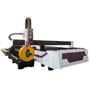
3. Geometric Precision in 3D Profiling
Unlike flat-sheet cutting, I-beam profiling requires a 5-axis or 6-axis kinematics system to navigate the complex geometry of the flanges and the web. The profiler utilizes a 3D cutting head capable of ±45-degree bevelling, essential for preparing weld joints (V, X, or K-shaped) directly on the machine. This eliminates the need for manual grinding or secondary bevelling stations.
In Houston’s railway infrastructure projects, the precision of bolt-hole alignment is paramount. Traditional punching or plasma cutting often results in tapered holes or heat-affected zones (HAZ) that can compromise the fatigue life of the rail splice. The 6000W laser maintains a hole-to-hole tolerance of ±0.1mm across a 12-meter beam, significantly exceeding AREMA (American Railway Engineering and Maintenance-of-Way Association) standards. The reduced HAZ minimizes the risk of micro-cracking, which is a critical failure mode in high-vibration railway environments.
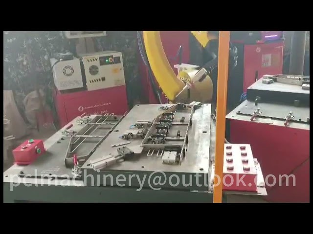
4. Analysis of Automatic Unloading Technology
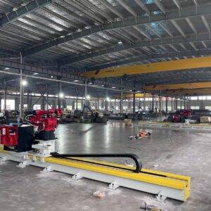
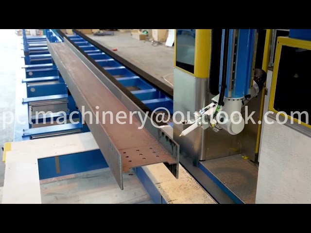
The most significant leap in efficiency observed in this field deployment is the transition from manual or crane-assisted unloading to a fully integrated automatic unloading system. In heavy-duty steel processing, the “arc-on” time is often secondary to the material handling time. An I-beam weighing several tons cannot be moved with the speed of sheet metal.
4.1. Mechanical Synchronicity and Buffer Logic
The automatic unloading system utilizes a series of servo-driven conveyors and pneumatic lifting rollers synchronized with the laser’s outfeed cycle. As the final cut—usually the parting cut—is completed, the system’s “intelligent grip” mechanism supports the finished part while the chucks release. This prevents the “drop-off” deformation that occurs when heavy sections are cut without support.
For Houston’s rail fabricators, this means the machine can transition from a finished 40ft I-beam to a fresh raw section in less than 90 seconds. Without automatic unloading, the crane wait-time and manual rigging typically result in 15 to 20 minutes of machine idle time per part. The efficiency gain is not merely additive; it is exponential when calculated over a three-shift production cycle.
4.2. Precision Preservation
Manual unloading of heavy structural members often leads to “mechanical scarring” or slight bending if the beam is not balanced correctly during the lift. The automatic system uses a multi-point support bed that ensures the beam remains perfectly planar during its transit from the cutting zone to the collection rack. This is particularly vital for the long-span beams used in Houston’s elevated rail interchanges, where even a 2mm deviation over 10 meters can complicate field assembly.
5. Application: Rail Infrastructure and Seismic Resilience
Houston’s geography requires infrastructure that can withstand both heavy freight loads and soil subsidence issues. The I-beams processed by the 6000W profiler are often used in “H-piles” and complex truss systems. The ability to laser-cut intricate “coping” cuts (the removal of a portion of the flange to allow the beam to join another at a 90-degree angle) with high precision allows for tighter fit-ups.
In structural engineering, a tighter fit-up translates to a more efficient weld. By using the 6000W laser, the “root gap” in welded connections is minimized and consistent. This leads to higher-quality welds with less filler metal required, reducing the overall weight of the structure while maintaining its load-bearing capacity—a key requirement for railway bridges spanning the Buffalo Bayou or intersecting major highways.
6. Synergy Between Laser Power and Automation
The synergy between the 6000W source and the automatic unloading system is managed via a centralized CNC controller running specialized nesting software. This software calculates the “nest” not just for material yield, but for unloading sequence. For example, it can prioritize cutting smaller segments (like mounting plates or stiffeners) from the same I-beam stock, which the unloading system then sorts into different bins, while the main beam continues to the primary discharge rack.
This level of “Total Process Control” reduces the labor overhead. A single operator can oversee the processing of 20 tons of steel per shift, whereas traditional methods would require a crew of four (operator, crane rigger, two assistants for deburring and marking). In Houston’s competitive labor market, this reduction in headcount while increasing throughput is a primary driver for the adoption of this technology.
7. Operational Challenges and Field Mitigation
During field testing in Houston, two primary challenges were identified: thermal lensing in high-humidity environments and material deviation in lower-grade structural steel.
- Thermal Lensing: The high humidity in Houston can lead to condensation in gas lines. We mitigated this by installing high-capacity refrigerated air dryers and using ultra-high purity (99.999%) Nitrogen as a shield gas, which also ensures an oxide-free cut edge ready for immediate painting or galvanizing.
- Material Deviation: Not all I-beams are perfectly straight from the mill. The 6000W profiler utilizes a laser-based “touch-probe” or “vision system” to scan the beam’s actual profile before cutting. The CNC then adjusts the cutting path in real-time to compensate for any “camber” or “sweep” in the raw material, ensuring that the bolt holes remain relative to the beam’s actual center line.
8. Conclusion
The deployment of the 6000W Heavy-Duty I-Beam Laser Profiler with Automatic Unloading represents a fundamental upgrade for Houston’s railway infrastructure sector. The technology moves beyond simple cutting; it provides an integrated material handling and precision machining solution that addresses the core inefficiencies of heavy steel fabrication. By eliminating secondary processing, reducing machine downtime through automated outfeed, and maintaining sub-millimeter tolerances, this system establishes a new technical benchmark for structural steel performance in the Gulf Coast region. The ROI is realized through a combination of reduced labor costs, zero-defect production, and significantly accelerated project timelines for critical transportation infrastructure.