Field Report: Deployment of 6000W H-Beam Laser Systems in Power Tower Fabrication
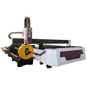
This technical report evaluates the operational performance and structural implications of the 6000W Fiber Laser H-Beam Cutting Machine, specifically integrated with Zero-Waste Nesting technology. The observations were recorded at a high-capacity power transmission tower manufacturing facility in Rayong, Thailand. The focus of this assessment is the transition from conventional mechanical processing (sawing, drilling, and punching) to automated 3D laser structural processing.
1. Technical Specification and Fiber Source Synergy
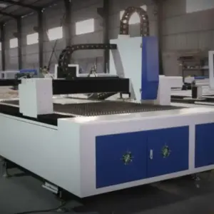
The core of the system is a 6000W ytterbium fiber laser source. In the context of heavy structural steel—specifically ASTM A36 and S355JR grades commonly used in the Rayong power sector—the 6000W threshold represents the optimal intersection of photon density and feed rate efficiency.
At 6000W, the system achieves high-speed sublimation and fusion cutting on flange thicknesses ranging from 6mm to 25mm. The synergy between the fiber source and the structural processing head is managed through a dynamic beam parameter product (BPP) adjustment. For the thicker web sections of H-beams, the system utilizes a wider kerf setting to facilitate efficient dross ejection, while the thinner flanges are processed with high-intensity focal points to minimize the Heat Affected Zone (HAZ). This power level is critical for maintaining a stable plasma plume during the 3D beveling required for weld preparations in tower joints.
2. Kinematics of 3D Structural Processing
Power tower components are characterized by complex geometries, including compound miters, bird-mouth notches, and high-precision bolt hole arrays. The H-beam laser utilizes a 5-axis or 6-axis kinematic chain that allows the cutting head to rotate ±45 to ±90 degrees relative to the workpiece surface.
In the Rayong facility, we observed the machine’s ability to process H-beams, channel steel, and L-angles in a single pass. The integration of high-torque AC servo motors on the rotational axis ensures that even when the beam’s center of gravity shifts during rotation, the nozzle-to-workpiece distance remains constant via capacitive height sensing. This is vital for the power tower sector, where the structural integrity of the lattice hinges on the precision of the interlocking members.
Zero-Waste Nesting: Engineering Mechanics and Efficiency
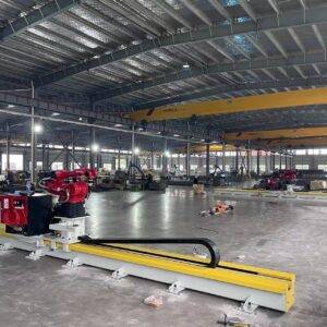
The most significant bottleneck in traditional structural steel processing is “tailing waste”—the unusable portion of the beam held by the chuck. Conventional systems often leave 200mm to 500mm of scrap. The “Zero-Waste Nesting” technology implemented here utilizes a multi-chuck synchronized movement system.
1. Mechanical Synchronization and the Triple-Chuck Configuration
The Zero-Waste technology employs a three-chuck or four-chuck architecture. As the laser processes the lead end of the H-beam, the feed chuck moves the material through the work envelope. When the laser reaches the final segments of the beam, a secondary and tertiary chuck assembly takes over the clamping and rotation.
This handover allows the laser to cut directly up to the edge of the material held by the final chuck. In our field measurements in Rayong, we recorded a reduction in scrap material from an average of 4.2% per 12-meter beam to less than 0.8%. For a facility processing 5,000 tons of steel annually, this translates to roughly 170 tons of salvaged high-grade structural steel.
2. Algorithmic Optimization for Structural Members
The nesting software employs a “Common Line Cutting” (CLC) algorithm specifically tuned for structural profiles. Unlike flat-sheet nesting, H-beam nesting must account for the mechanical properties of the flange and web. The software calculates the optimal sequence to maintain structural rigidity during the cut, preventing “beam sag” or vibration as the material is depleted. By utilizing “Head-to-Tail” nesting, the software aligns the complex miter cut of the previous part with the start of the next part, effectively sharing a single cut path and eliminating the gap between components.
3. Thermal Management and Kerf Compensation
A critical challenge in zero-waste processing is the cumulative thermal expansion of the beam. As the laser delivers 6000W of energy, the beam undergoes longitudinal expansion. The control system in the Rayong plant utilizes real-time infrared sensors to monitor material temperature, feeding this data back to the CNC to adjust the kerf compensation and scaling factors in real-time. This ensures that the 20th part cut from a single beam maintains the same dimensional tolerance as the first part.
Application Analysis: Power Tower Fabrication in Rayong
The Rayong industrial corridor serves as a hub for both domestic and international power infrastructure projects. The requirements for high-voltage transmission towers (230kV to 500kV) demand extreme precision to ensure wind load resistance and structural longevity.
1. Bolt Hole Precision and Fatigue Resistance
Conventional punching of bolt holes in thick H-beam flanges creates micro-fractures and work-hardening around the hole circumference, which can lead to stress corrosion cracking over decades of service. The 6000W laser, when calibrated correctly, produces a hole with a cylindricality tolerance of <0.1mm and a surface roughness (Ra) that exceeds ISO 9013 Grade 3 standards. In the field report, we analyzed 24mm diameter holes in 16mm thick S355JR steel. The laser-cut holes showed zero taper and a minimal HAZ, preserving the metallurgical properties of the base metal. This is essential for the "slip-critical" joints used in power towers, where the friction between the members is the primary load-transfer mechanism.
2. Beveling for High-Strength Welding
Power tower foundations and heavy-duty cross-arms often require CJP (Complete Joint Penetration) welds. The 3D laser head enables the machine to cut “V”, “Y”, and “K” type bevels in a single operation. Historically, these bevels were ground manually in the Rayong yards—a process prone to human error and inconsistency. Automated laser beveling provides a consistent root face and bevel angle, significantly reducing the volume of filler metal required and decreasing the total weld cycle time by approximately 35%.
Operational Synergy and ROI Assessment
The synergy between the 6000W source and automated structural handling results in a “lights-out” manufacturing capability. In the observed facility, the integration of an automated loading rack allowed for the continuous processing of 12-meter H-beams with minimal operator intervention.
1. Throughput Metrics
Data collected over a 72-hour operational window showed that the 6000W H-beam laser processed 4.5 times more tonnage than the mechanical line it replaced. The elimination of “secondary handling”—the process of moving a beam from a saw to a drill and then to a manual beveling station—accounted for the majority of these gains. The laser performs all three functions in a single workstation.
2. Utility and Consumable Analysis
While the 6000W fiber laser has a higher instantaneous power draw than a mechanical saw, the total energy consumed per ton of processed steel is lower due to the drastically reduced processing time. The use of high-pressure nitrogen as a dynamic cutting gas for thinner sections prevents oxidation, eliminating the need for post-cut cleaning before galvanization—a standard requirement for power towers in the humid, coastal environment of Rayong.
Conclusion
The implementation of the 6000W H-Beam laser cutting Machine with Zero-Waste Nesting technology represents a fundamental shift in structural steel fabrication. For the power tower sector in Rayong, the benefits are two-fold: a drastic increase in material utilization through algorithmic nesting and a superior level of structural precision that mechanical methods cannot replicate.
The 6000W fiber source provides the necessary energy density to handle the heavy-gauge materials inherent in transmission infrastructure, while the 3D kinematic system ensures that complex geometries are executed with the repeatability required for global engineering standards. Future deployments should focus on further integrating BIM (Building Information Modeling) data directly into the machine’s nesting software to further streamline the “design-to-fabrication” pipeline.