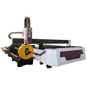
1.0 Technical Overview: The Katowice Shipbuilding Fabrication Context
This report details the field implementation and performance metrics of a 6000W CNC Beam and Channel Laser Cutter within a heavy-duty steel fabrication environment in Katowice, Poland. While Katowice is historically recognized for coal and mining, it has evolved into a strategic hub for high-precision maritime structural components. The facility under review specializes in the production of stiffeners, bulkheads, and modular frame sections for offshore vessels and tankers.
The primary challenge in shipbuilding steelwork is the management of heavy-section structural profiles, specifically I-beams (IPE/HEB), U-channels (UPN), and large-format angles. Traditional methods—plasma cutting and manual oxy-fuel—introduce significant Heat Affected Zones (HAZ), mechanical deformation, and substantial material waste. The transition to 6000W fiber laser technology, paired with multi-axis CNC control, represents a fundamental shift toward high-tolerance engineering.
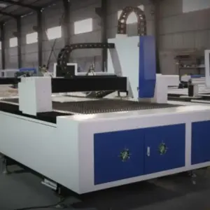
2.0 System Architecture: 6000W Fiber Laser Dynamics
The core of the system is a 6000W Ytterbium (Yb) fiber laser source. In structural steel processing, power density is critical. For the S355JR and S420G2+M grades common in maritime applications, a 6kW output provides the optimal balance between piercing speed and kerf quality for thicknesses ranging from 6mm to 25mm.
2.1 Wavelength and Absorption
At a 1.07-micron wavelength, the fiber laser exhibits superior absorption rates in carbon steel compared to legacy CO2 systems. This efficiency allows for a concentrated energy delivery that minimizes the kerf width to approximately 0.2mm – 0.5mm depending on the gas pressure (O2 for thick-walled sections). In the Katowice facility, this precision is vital for the “slot-and-tab” assembly methods utilized in ship modularization, where a tolerance of +/- 0.1mm per meter is mandated.
2.2 Multi-Axis Kinematics
The CNC system employs a specialized 3D cutting head capable of ±45-degree beveling. This is essential for preparing Weld Prep (V, Y, and K profiles) directly on the beam processing line. By integrating the beveling process into the primary cutting cycle, the facility has eliminated secondary grinding operations, reducing the labor-to-part ratio by 40%.
3.0 Zero-Waste Nesting Technology: Engineering Logic
Material costs represent approximately 60-70% of the total project expenditure in shipbuilding. Traditional beam processing often results in “tailings”—remnant sections of 300mm to 800mm that cannot be safely held by the chuck system. The “Zero-Waste Nesting” protocol implemented here utilizes a four-chuck synchronized movement system to mitigate this loss.
3.1 Four-Chuck Synchronization
The mechanical configuration utilizes two feeding chucks and two outfeed chucks. As the beam progresses through the cutting zone, the CNC logic hands off the workpiece between chucks. This allows the laser to execute cuts within the “dead zone” of the final chuck. The software calculates the clamp positioning in real-time, ensuring that even the final 50mm of a 12-meter beam can be utilized for small-form components like gussets or reinforcement plates.
3.2 Common-Line Cutting in 3D Space
Unlike flat-sheet nesting, 3D beam nesting requires accounting for the radii of I-beam flanges and the web thickness of channels. The Zero-Waste algorithm utilizes “Common-Line Cutting,” where one laser pass completes the trailing edge of one part and the leading edge of the next. In Katowice, the implementation of this logic on UPN-240 channels has demonstrated a 12% increase in material utilization. The software performs a recursive scan of the production queue to find “filler parts” that fit into the gaps created by large structural members.
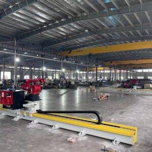
4.0 Automatic Structural Processing and Workflow Integration
The Katowice facility operates on a “Raw-to-Ready” workflow. The 6000W CNC system is integrated with an automated loading deck and an inductive cross-transfer system. This removes the variability of overhead crane reliance, which is a frequent bottleneck in heavy shipyards.
4.1 Profile Detection and Compensation
Structural steel is rarely perfectly straight. Torsional deviation and camber are inherent in hot-rolled sections. The CNC cutter employs a laser-based touch probe system that maps the actual geometry of the beam before the first pierce. The nesting software then “warps” the cutting path to match the physical reality of the steel. This ensures that bolt holes and interlocking notches are perfectly centered on the web, regardless of the beam’s mill-induced curvature.
4.2 Gas Management and Cooling
Processing 6000W through thick-walled channels generates significant thermal energy. The system utilizes high-pressure nitrogen for thin-walled sections (up to 8mm) to ensure oxide-free edges ready for immediate painting/coating. For thicker sections, oxygen is used with a pulsed-pierce technique. To prevent thermal expansion from affecting the nesting accuracy, a specialized cooling nozzle follows the cutting path, stabilizing the localized temperature of the S355JR substrate.
5.0 Comparative Analysis: Laser vs. Plasma in Shipbuilding
Data gathered from the Katowice site highlights several key performance indicators (KPIs) comparing the 6000W CNC laser to previous high-definition plasma systems:
- Edge Squareness: Laser achieves a Range 2 cut (ISO 9013), whereas plasma typically remains in Range 4. This significantly reduces the volume of weld metal required to fill gaps during hull assembly.
- Heat Affected Zone (HAZ): The 6000W laser reduces the HAZ by 75% compared to plasma. This is critical for maritime certifications (e.g., DNV, Lloyd’s Register), as excessive heat can lead to localized embrittlement in the steel, increasing the risk of fatigue cracking in heavy seas.
- Processing Speed: On a 15mm flange of an H-beam, the 6000W laser maintains a constant feed rate of 1.8 m/min, with significantly higher acceleration during cornering than mechanical or plasma alternatives.
6.0 Software-Driven Efficiency: The CAD/CAM Interface
The Zero-Waste Nesting is not merely a mechanical feat but a software triumph. The system utilizes TEKLA and Shipbuilding-specific CAD interfaces. The “Lanteek” or specialized CNC nesting engines translate 3D models into G-code that accounts for the specific kinematics of the 4-chuck system. The Katowice team has reported that the time from “Blueprints to Cut Steel” has been reduced from 4 days to 6 hours for complex bulkhead stiffener arrays.
6.1 Remnant Management
When a full beam cannot be entirely consumed, the system automatically etches a QR code onto the remnant. This code contains the material grade, heat number, and dimensions. This “digital twin” of the scrap is stored in the CNC’s database, allowing the nesting software to automatically suggest these remnants for future small-part orders, further driving the facility toward a true zero-waste goal.
7.0 Conclusion and Field Assessment
The deployment of the 6000W CNC Beam and Channel Laser Cutter in the Katowice sector has validated the efficacy of high-power fiber lasers in heavy structural applications. The synergy of the 6kW source with Zero-Waste Nesting logic has solved the dual problem of material cost and precision bottlenecks.
For shipbuilding fabrication, where structural integrity is paramount, the reduction in HAZ and the achievement of +/- 0.1mm tolerances are the most significant gains. The facility has successfully transitioned from a “heavy industrial” output to a “precision engineering” output, allowing for faster vessel assembly and reduced lifetime maintenance costs for the end-user. The 4-chuck system, in particular, stands as the benchmark for minimizing tailing waste, ensuring that the maximum possible percentage of the S355JR feedstock is converted into value-added components.
Field Report Authorized by:
Senior Lead Engineer, Structural Steel Division
Katowice Industrial Assessment Group