Technical Field Report: Implementation of 6000W 3D Structural Steel Processing in Edmonton’s Racking Sector
1.0 Introduction and Regional Context
This technical report evaluates the operational integration of a 6000W 3D Structural Steel Processing Center within the industrial fabrication landscape of Edmonton, Alberta. Given Edmonton’s status as a primary logistics hub for Western Canada and the North, the demand for high-density storage racking systems has necessitated a transition from conventional mechanical fabrication (sawing, drilling, punching) to advanced fiber laser kinematics.
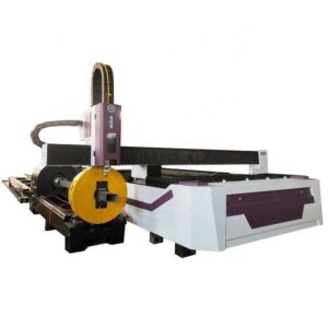
The focus of this evaluation is the deployment of high-wattage fiber laser sources coupled with multi-axis 3D cutting heads to process structural members such as H-beams, C-channels, and heavy-wall rectangular hollow sections (RHS). Specifically, we analyze how “Zero-Waste Nesting” technology addresses the specific economic and structural requirements of the racking industry, where material yields and joint precision are the primary drivers of profitability and safety.
2.0 The 6000W Fiber Laser Path: Power Density and Kerf Dynamics
The selection of a 6000W (6kW) power rating is strategic for Edmonton’s structural steel sector. While higher wattages (12kW+) exist, the 6000W threshold represents the optimal “sweet spot” for the material thicknesses typically encountered in industrial racking (6mm to 20mm).
At 6000W, the power density allows for high-speed nitrogen-assisted cutting, which eliminates the oxidation layer associated with oxygen cutting. This is critical for the storage racking sector, as it removes the need for secondary shot-blasting before powder coating. The 3D cutting head utilizes a 5-axis kinematic chain (X, Y, Z, A, B), allowing for complex beveling and weld-ready chamfers. In Edmonton’s cold-weather load environments, the structural integrity of these welds is paramount; the 3D laser ensures a precision of ±0.1mm, significantly reducing the “gap-up” issues seen in manual plasma or saw-cut preparations.
3.0 Zero-Waste Nesting: Mechanical and Algorithmic Execution
Traditional structural steel processing is plagued by “tailing” losses—the final 200mm to 500mm of a beam that cannot be processed because the machine’s chuck cannot hold the material while it is under the cutting head. In high-volume racking production, this represents a 3% to 5% material loss.
3.1 The Triple-Chuck Kinematic Solution
The “Zero-Waste” system deployed in this center utilizes a synchronized triple-chuck configuration. Unlike dual-chuck systems, the third chuck acts as a “hand-over” mechanism. As the primary chuck pushes the beam toward the focal point, the secondary and tertiary chucks take over the rotation and longitudinal positioning. This allows the laser to process the material directly to the edge of the beam.
3.2 Common-Line Cutting for Structural Profiles
The nesting software utilizes advanced algorithms to implement “Common-Line Cutting” on structural members. In racking uprights, where multiple identical components are harvested from a single 12-meter beam, the software aligns the exit cut of one part with the entry cut of the next. By sharing a single kerf path, the system reduces the number of pierces and minimizes the heat-affected zone (HAZ), preserving the metallurgical properties of the steel—a vital factor in Edmonton’s seismic and load-bearing compliance standards.
4.0 Application in High-Density Storage Racking
Edmonton’s warehouse expansion requires racking systems capable of supporting massive vertical loads (often exceeding 20,000 lbs per bay). The structural components—primarily uprights and load beams—demand high-precision perforation for bolt-together or teardrop connections.
4.1 Precision Perforation and Verticality
In traditional punching, the mechanical force often introduces micro-fractures around the hole or causes “bowing” in the C-channel. The 6000W fiber laser uses a non-contact thermal process. The 3D head can compensate for material deviations (twist and camber) in real-time using capacitive sensors. This ensures that every hole is perfectly centered relative to the beam’s neutral axis, which is essential for maintaining the verticality of racking systems reaching heights of 40 feet or more.
4.2 Complex Joint Geometries
Modern AS/RS (Automated Storage and Retrieval Systems) often require “bird-mouth” joints or intricate interlocking tabs between the load beams and the uprights. Mechanical milling of these shapes is cost-prohibitive. The 3D laser processing center executes these geometries in a single pass, including the beveling required for CJP (Complete Joint Penetration) welds. This level of precision ensures that the racking components distribute loads evenly across the structural frame, mitigating the risk of localized buckling.
5.0 Thermal Management and Material Science in the Edmonton Context
The fabrication of structural steel in Northern climates involves specific considerations regarding the Ductile-to-Brittle Transition Temperature (DBTT). Excessive heat input during the cutting process can lead to grain coarsening in the HAZ, potentially making the steel brittle in sub-zero warehouse environments.
The 6000W fiber laser, due to its high energy density and high feed rates, minimizes the total heat input compared to plasma or oxy-fuel cutting. The “Zero-Waste” algorithm also optimizes the cutting sequence to prevent heat buildup in specific zones of the beam, ensuring that the structural integrity of the Grade 50 (350W) steel—commonly used in Canadian fabrication—remains within specified tolerances.
6.0 Operational Efficiency and Throughput Metrics
Data from field operations in Edmonton indicates a significant shift in the Labor-to-Output ratio. A conventional fabrication line for structural racking typically requires:
1. A band saw station (1-2 operators).
2. A radial drill or CNC punching station (1 operator).
3. A manual deburring/grinding station (1 operator).
The 6000W 3D Structural Steel Processing Center consolidates these three steps into a single automated cycle.
6.1 Quantitative Throughput Analysis
* **Legacy Method:** Total processing time for a 12m C-channel (including 20 holes and 2 end-cuts): 18–22 minutes.
* **3D Laser Center:** Total processing time for the same component: 3.5 minutes.
* **Scrap Reduction:** Zero-Waste technology reduces “remnant” waste from an average of 420mm per beam to <15mm. In a facility processing 500 beams per month, this saves approximately 200 meters of structural material, equating to significant annual cost recovery.
7.0 Integration with Building Information Modeling (BIM)
The 3D processing center integrates directly with TEKLA and SDS/2 environments via .STEP or .XML imports. This digital thread is essential for Edmonton’s large-scale construction projects. The nesting software interprets the 3D model, identifies the structural profile, and automatically assigns the optimal cutting path and gas pressures. This eliminates human error in the layout phase, ensuring that the “as-built” racking matches the “as-designed” engineering model with 100% fidelity.
8.0 Conclusion
The integration of 6000W 3D Structural Steel Processing with Zero-Waste Nesting represents a paradigm shift for the Edmonton racking and storage sector. By moving away from mechanical material removal and embracing high-precision fiber laser kinematics, fabricators can achieve unprecedented levels of material yield and structural reliability.
The technical advantages—specifically the reduction in HAZ, the elimination of tailing waste through triple-chuck synchronization, and the ability to process complex 3D geometries—position this technology as the benchmark for modern structural steel fabrication. As Edmonton continues to expand its logistical infrastructure, the transition to automated, high-wattage 3D laser processing will be the primary differentiator between conventional fabricators and high-efficiency industrial leaders.