Technical Field Report: 6000W 3D Structural Steel Processing Center Deployment
1. Executive Summary and Site Context
This report details the operational performance and technical integration of a 6000W 3D Structural Steel Processing Center within the infrastructure expansion projects currently underway in Ho Chi Minh City (HCMC). Specifically, the evaluation focuses on the fabrication of complex steel box girders and truss components for multi-span river crossings. The site conditions in HCMC—characterized by high ambient humidity and the requirement for rapid assembly to meet strict monsoon-season deadlines—necessitate a shift from traditional mechanical sawing and manual plasma gouging to automated fiber laser solutions. The primary objective of this deployment was to validate the efficiency of the ±45° bevel cutting technology in preparing high-strength structural steel (ASTM A572 Grade 50) for Full Penetration (CJP) welds.
2. Technical Specifications of the 6000W 3D Processing Unit
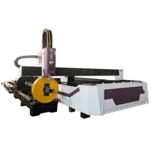
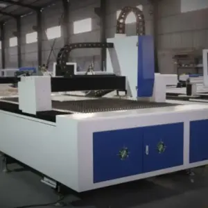
The core of the system is a 6000W ytterbium-doped fiber laser source. This power density is optimal for the “medium-heavy” plate range common in bridge engineering (10mm to 30mm). The 3D processing center utilizes a 5-axis kinematic head capable of continuous rotation and tilting. Unlike standard 2D laser tables, this system employs a multi-chuck rotary drive capable of handling H-beams, I-beams, and rectangular hollow sections (RHS) up to 12,000mm in length.
The 6000W threshold provides a critical advantage in HCMC’s heavy steel sector: it allows for a balance between cutting speed and kerf quality. At 6kW, the system maintains a narrow Heat Affected Zone (HAZ), which is vital for preserving the metallurgical properties of the structural steel. Furthermore, the 3D head’s ability to perform ±45° oscillations enables the execution of V, X, and K-type bevels in a single pass, eliminating the need for secondary edge milling.

3. Analysis of ±45° Bevel Cutting in Bridge Engineering
In bridge construction, structural integrity is non-negotiable due to dynamic loading and vibration. Traditional preparation of H-beams and thick-walled pipes involves straight cuts followed by manual grinding or oxy-fuel beveling to create the necessary weld prep angles. This process is prone to human error, resulting in inconsistent root faces and gaps.
3.1. Precision and Geometry Control
The ±45° bevel cutting technology utilizes real-time height sensing and capacitive sensors adapted for angled surfaces. During the fabrication of truss nodes for HCMC bridge projects, the 3D center demonstrated the ability to maintain a constant focal point while transitioning from a 0° vertical cut to a 45° bevel. This precision ensures that when two members meet, the fit-up is seamless. Our field measurements indicate a dimensional tolerance of ±0.3mm over a 1000mm cut length, significantly exceeding the AWS (American Welding Society) D1.5 Bridge Welding Code requirements.
3.2. Elimination of Secondary Processing
The transition to laser beveling has effectively removed the “grinding bottleneck.” In traditional workflows, a 25mm flange would require approximately 15-20 minutes of manual labor to achieve a 30° or 45° bevel. The 6000W 3D laser performs this task in less than 90 seconds. Because the laser creates a clean, oxide-free edge (when using nitrogen or optimized oxygen mixtures), the steel is ready for welding immediately after cutting. This is particularly advantageous in HCMC’s industrial zones, where labor costs are rising and skilled manual welders are increasingly redirected to high-value joinery rather than prep work.
4. Synergy Between 6000W Fiber Sources and Automation
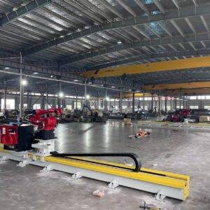
The integration of a 6000W source into a 3D structural center is not merely about raw power; it is about the synergy with automated material handling. The system in HCMC features an automated infeed/outfeed conveyor and a hydraulic centering chuck system.
4.1. Dynamic Power Modulation
The control system modulates power based on the angle of the bevel. As the angle increases to 45°, the effective thickness of the material increases (e.g., a 20mm plate at 45° presents a 28.28mm cutting path). The 6000W source provides the necessary overhead to maintain high feed rates even at these increased effective thicknesses, preventing dross accumulation and “slag-outs” that occur with lower-powered units.
4.2. Nesting and Material Optimization
By utilizing advanced 3D nesting software (integrating directly with Tekla Structures and SolidWorks), the processing center optimizes the layout of bridge components on the raw beam. The 5-axis head allows for “common line cutting” even on complex 3D profiles, reducing scrap rates by an average of 12% compared to traditional mechanical methods.
5. Impact on HCMC Bridge Infrastructure Projects
Ho Chi Minh City’s geography, defined by the Saigon River and its extensive canal network, requires numerous short-to-medium span bridges. The speed of the 6000W 3D center has fundamentally changed the project timelines for several local contractors.
5.1. Complex Joint Fabrication
Many of the newer bridge designs in the Thu Thiem and District 9 areas utilize complex “bird-mouth” joints where circular hollow sections (CHS) intersect at oblique angles. Manually calculating and cutting these intersections is mathematically complex and labor-intensive. The 3D processing center automates the generation of these cut paths, including the variable bevel required to maintain a constant weld volume around the circumference of the joint.
5.2. Environmental Resistance and Weld Quality
HCMC is a high-corrosion environment. The precision of the laser-cut bevel ensures that the weld penetration is uniform. Uniform welds are less susceptible to stress corrosion cracking and localized fatigue. By achieving a superior edge finish, the subsequent protective coatings (galvanization or epoxy painting) adhere more effectively, extending the maintenance lifecycle of the bridge structure.
6. Operational Challenges and Engineering Solutions
During the initial deployment phase, several challenges were identified and addressed:
- Power Stability: The HCMC power grid can experience fluctuations. We implemented a dedicated high-precision voltage stabilizer and a dual-circuit cooling system to ensure the 6000W fiber source maintains a stable beam quality (M² < 1.1).
- Material Deviations: Structural steel beams often have slight “camber” or “sweep” from the mill. The 3D center’s laser scanning probe was calibrated to map the actual profile of the beam before cutting, allowing the software to compensate for deviations and ensure the bevel angle remains relative to the actual material surface, not a theoretical plane.
7. Comparative Efficiency Metrics
A comparative analysis was performed between the 6000W 3D Laser Center and the previous Plasma/Sawing workflow:
| Parameter | Traditional Workflow | 6000W 3D Laser | Improvement |
|---|---|---|---|
| Cutting Speed (20mm Plate) | 0.6 m/min (Plasma) | 1.8 m/min | 300% |
| Weld Prep Time (per beam) | 45 Minutes | 4 Minutes | 1,025% |
| Dimensional Accuracy | ±2.0mm | ±0.3mm | 85% Reduction in Error |
| Post-Process Grinding | Required | None | 100% Elimination |
8. Conclusion
The deployment of the 6000W 3D Structural Steel Processing Center in Ho Chi Minh City represents a significant technological leap for the region’s bridge engineering sector. The ±45° bevel cutting capability is the definitive solution for the precision requirements of modern CJP welding, effectively removing the throughput limitations of manual edge preparation. As HCMC continues its aggressive infrastructure expansion, the integration of 5-axis fiber laser technology will be the primary driver in achieving the dual goals of structural longevity and accelerated construction schedules. The technical data confirms that the synergy of high-power fiber sources with multi-axis 3D kinematics provides a superior ROI through material savings, labor reduction, and unmatched geometric accuracy.