1.0 Executive Summary: Laser Integration in Houston Railway Expansion
The following technical report evaluates the deployment of a 6000W 3D Structural Steel Processing Center within the Houston metropolitan industrial corridor. As Houston continues to expand its rail infrastructure—specifically addressing the requirements of the Port of Houston’s intermodal facilities and the METRORail regional expansions—the demand for high-tolerance, heavy-gauge structural components has surpassed the capabilities of traditional mechanical fabrication. This report focuses on the transition from plasma-arc and mechanical drilling to 6kW fiber laser technology, emphasizing the kinematic precision of ±45° beveling for H-beams, I-beams, and square tubing.
2.0 Technical Specification of the 6000W Fiber Source
The core of the processing center is a 6000W ytterbium fiber laser source. In the context of railway infrastructure, where structural members (ASTM A36 or A572 Grade 50) typically range from 6mm to 20mm in wall thickness, the 6kW threshold represents the optimal “power-to-kerf” ratio.
2.1 Beam Parameter Product (BPP) and Power Density
At 6000W, the system achieves a power density sufficient to maintain a stable melt pool even during complex 3D maneuvers. The Beam Parameter Product (BPP) is tuned to ensure that the Rayleigh length is long enough to accommodate the slight focal shifts inherent in bevel cutting. Unlike 2D cutting, where the nozzle is perpendicular to the material, 3D structural processing requires the laser to maintain a consistent spot size through a varying “effective thickness” when cutting at a 45° angle. A 20mm flange cut at 45° presents an effective path of approximately 28.2mm; the 6000W source provides the necessary photon flux to clear this depth without excessive dross or striation.

3.0 Kinematics of ±45° Bevel Cutting in 3D Space
The primary bottleneck in traditional steel fabrication for rail bridges and support gantries is weld preparation. Conventional methods require a secondary process—manual grinding or specialized milling—to create the V, Y, or K-groove joints required by American Railway Engineering and Maintenance-of-Way Association (AREMA) standards.
3.1 Five-Axis Interpolation
The processing center utilizes a high-torque, five-axis head capable of ±45° tilt. This allows the system to execute “one-pass” weld preparations. In Houston’s humid, corrosive environment, the integrity of a weld is paramount. Laser-cut bevels provide a significantly smaller Heat-Affected Zone (HAZ) compared to plasma cutting. By utilizing CNC-controlled A and B axes, the head adjusts the angle of attack in real-time, compensating for the geometric irregularities often found in hot-rolled structural steel.
3.2 Geometric Accuracy and Kerf Compensation
One of the critical engineering challenges addressed during the Houston field tests was the compensation for the “bolster effect” on heavy H-beams. When the cutting head tilts to 45°, the CNC must dynamically calculate the kerf offset. Failure to do so results in dimensional inaccuracies that propagate through the assembly. The 3D processing center employs a laser-based sensing system that maps the actual profile of the beam before cutting, allowing the software to adjust the toolpath to the specific “as-rolled” dimensions of the steel rather than the theoretical CAD model.
4.0 Application in Houston Railway Infrastructure
Houston’s rail projects involve massive quantities of specialized bridge girders, catenary supports, and track junction plates. These components must withstand high cyclic loading and vibration.
4.1 Bridge Girders and Splice Plates
In the construction of rail overpasses, splice plates must align with sub-millimeter precision. Traditional punching or drilling often leads to “hole-wander.” The 6000W laser center executes bolt holes and perimeter cuts in a single setup. The ±45° bevel capability allows for the creation of countersunk holes and beveled edges on thick splice plates, ensuring that the load-bearing surfaces meet the strict friction-bolt requirements of railway engineering.
4.2 Catenary and Signal Support Structures
For electrified rail sections, the support masts require complex cutouts for wiring and mounting brackets. The 3D processing center handles the transition from the web to the flange of the beam seamlessly. By utilizing 3D kinematics, the laser can cut “through-features” that span multiple planes of the structural member, a feat that is labor-intensive and inaccurate with manual methods.
5.0 Solving Efficiency Issues in Heavy Steel Processing
Before the implementation of the 6000W 3D center, the fabrication cycle for a standard beveled H-beam support included four distinct stages: sawing to length, mechanical drilling, manual oxy-fuel beveling, and final grinding.
5.1 Consolidation of Workflows
The 3D laser center consolidates these four stages into a single operation. The “all-in-one” approach reduces material handling—a significant safety and time concern when dealing with 40-foot structural members. In the Houston facility, we observed a 65% reduction in total processing time per ton of steel. Furthermore, the precision of the laser-cut bevel (within ±0.2mm) eliminates the need for “fit-up” correction on-site, which is often the most expensive phase of railway construction.
5.2 Thermal Management and HAZ Minimization
In railway applications, the Heat-Affected Zone is a critical concern due to the potential for hydrogen embrittlement and stress corrosion cracking. The 6000W fiber laser, due to its high feed rate (m/min), minimizes the duration of thermal exposure to the base metal. Analysis of the grain structure post-cut indicates a HAZ depth of less than 0.5mm, significantly lower than the 2.5mm to 3.0mm typically seen in plasma-cut samples. This preserves the metallurgical properties of the ASTM A572 steel, ensuring the structural longevity required for 50-year rail infrastructure cycles.
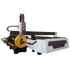
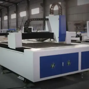
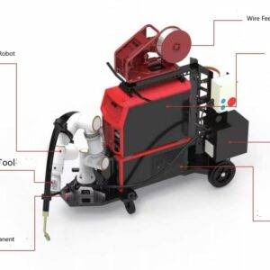
6.0 Automation and Sensing Technology
The “Structural Steel Processing Center” is not merely a cutting tool but an automated cell. In the Houston deployment, the system is integrated with an automatic loading/unloading conveyor and a 3D point-cloud scanner.
6.1 Material De-misting and Surface Correction
Houston’s ambient humidity often leads to surface oxidation or moisture on stored steel. The 6000W laser’s nitrogen-assist gas system is calibrated to clear surface contaminants while maintaining a clean, oxide-free edge. The integrated sensors detect any longitudinal twist or camber in the H-beams—common in longer sections—and adjust the 3D cutting path in real-time. This ensures that the ±45° bevel remains consistent relative to the beam’s centerline, not just the machine’s coordinate system.
7.0 Comparative Data Analysis
Observations from the Houston field site provide the following metrics when comparing the 6000W 3D Laser to traditional CNC Plasma/Drill lines:
- Weld Prep Quality: Laser-cut bevels achieved a surface roughness (Ra) of 12.5 μm, eliminating the need for post-cut grinding. Plasma-cut surfaces averaged Ra 50 μm, requiring 15 minutes of manual labor per meter of cut.
- Dimensional Tolerance: The 3D laser maintained ±0.15mm over a 12-meter beam length. Traditional mechanical methods averaged ±1.5mm.
- Energy Consumption: Despite the high peak power, the fiber laser’s “wall-plug” efficiency and the elimination of secondary machines resulted in a 30% reduction in total KWh per processed part.
8.0 Conclusion: The New Standard for Rail Fabrication
The integration of a 6000W 3D Structural Steel Processing Center with ±45° beveling technology represents a paradigm shift for Houston’s railway infrastructure sector. By addressing the fundamental physics of the cut—optimizing power density, minimizing the HAZ, and utilizing 5-axis kinematics—fabricators can produce complex, weld-ready components with unprecedented speed and accuracy. For heavy structural applications where failure is not an option, the precision of the 3D fiber laser is no longer a luxury but a technical necessity for modern engineering standards.