1.0 Introduction: The Industrial Context of Haiphong Crane Manufacturing
The maritime and logistics infrastructure in Haiphong, Vietnam, has necessitated a radical shift in the fabrication of heavy-lifting equipment. Crane manufacturing—encompassing Ship-to-Shore (STS) cranes, Rubber-Tired Gantry (RTG) cranes, and heavy industrial overhead systems—relies heavily on the structural integrity of large-scale profiles. Traditionally, the processing of H-beams, I-beams, and C-channels in this sector involved a fragmented workflow: mechanical sawing, followed by radial drilling, and manual plasma beveling for weld preparation.
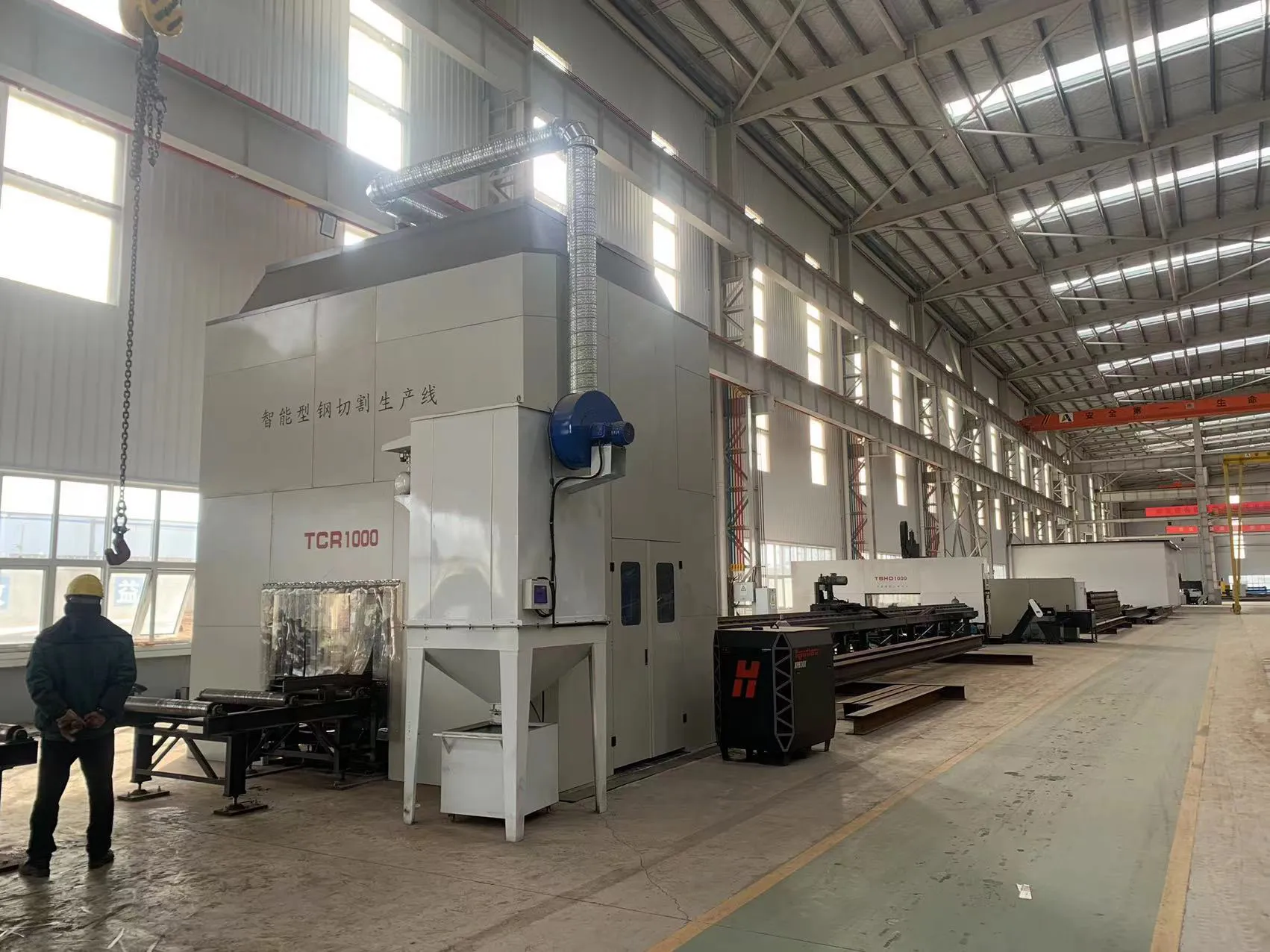
The introduction of the 30kW Fiber Laser Universal Profile Steel Laser System represents a paradigm shift. By integrating high-density photonic energy with multi-axis kinematics and automated material handling, the system addresses the critical requirements of the Haiphong industrial zone: high throughput, extreme dimensional accuracy, and reduced labor dependency in high-humidity maritime environments.
2.0 30kW Fiber Laser Source: Energy Density and Gas Dynamics
The core of this system is the 30kW ytterbium fiber laser source. In the context of crane structural components—where flange thicknesses frequently range from 12mm to 30mm—the 30kW threshold is not merely about speed; it is about the physics of the melt pool and the quality of the kerf.
2.1 Cutting Speed and Thermal Gradient
At 30kW, the energy density allows for significantly higher feed rates compared to 12kW or 20kW alternatives. For a standard 25mm thick Q355B H-beam web, the 30kW system maintains a stable vaporized cutting state rather than a simple melt-and-blow process. This minimizes the Heat-Affected Zone (HAZ), which is critical for crane manufacturing where grain structure alteration can lead to fatigue failure in high-stress joints.
2.2 Gas Dynamics and Nozzle Technology
High-power cutting requires sophisticated auxiliary gas management. In the Haiphong field application, we utilize high-pressure Nitrogen for stainless components or Oxygen for carbon steel. The 30kW head utilizes a cooled, high-speed nozzle assembly that maintains a laminar gas flow. This ensures that dross adhesion is virtually eliminated on the underside of the profile flanges, removing the need for secondary grinding—a major bottleneck in traditional crane girder fabrication.
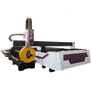
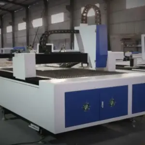
3.0 Kinematics of the Universal Profile System
The “Universal” designation refers to the system’s ability to process various geometries—H, I, L, U, and T profiles—within a single CNC environment. This is achieved through a multi-chuck 3D configuration and a 5-axis (or 6-axis) cutting head.
3.1 Multi-Chuck Stability
In crane manufacturing, profiles often exceed 12 meters in length. The system utilizes a four-chuck synchronized drive. This configuration is essential for maintaining the axial center line of heavy profiles that may have inherent mill-run deviations or slight longitudinal twisting. The four-chuck system provides the necessary torque to rotate multi-ton beams while maintaining a positioning accuracy of ±0.05mm per meter.
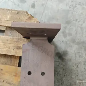
3.2 3D Beveling for Weld Preparation
Structural crane components require complex weld preps, including K, V, and Y-type bevels. The 30kW system’s 5-axis head allows for ±45° inclination during the cutting process. By integrating the beveling directly into the profile cutting cycle, we eliminate the need for manual oxy-fuel beveling. This ensures that the root face and bevel angle are mathematically consistent, leading to higher-quality robotic welding passes in subsequent assembly stages.
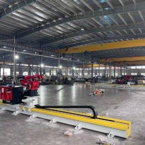
4.0 Automatic Unloading Technology: Solving the Heavy Steel Bottleneck
The processing of heavy steel is often hindered not by the cutting speed, but by the logistics of material handling. A 12-meter H-beam is a high-mass object that presents significant safety and deformation risks during unloading.
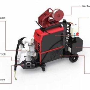
4.1 Mechanical Logic of the Unloading Bed
The Automatic Unloading system utilizes a series of servo-driven hydraulic lift-and-transfer arms. As the 30kW head completes the final cut, the unloading logic synchronizes with the chuck release. The finished profile is supported across its entire length to prevent sagging or “whiplash” deformation, which is common when using overhead cranes for small-piece removal.
4.2 Integration with Buffer Zones
In the Haiphong facility, the unloading system feeds directly into a lateral conveyor buffer zone. This allows the laser to begin processing the next profile immediately without waiting for an overhead crane operator. The “Universal” nature of the system means it can unload a 200mm C-channel and a 600mm H-beam sequentially without manual adjustment of the unloading grippers, thanks to adaptive sensor arrays that detect the profile’s cross-sectional center of gravity.
5.0 Field Observations: Precision and Efficiency in Haiphong
During the commissioning phase in Haiphong, specific performance metrics were established to compare the 30kW laser system against legacy plasma and mechanical methods.
5.1 Dimensional Accuracy and Hole Alignment
Crane trolley rails and end carriages require precise hole patterns for bolting. Traditional drilling often suffers from “bit wander” on thick-walled profiles. The 30kW laser achieves a circularity tolerance of ±0.1mm on 25mm thick flanges. In the field, this has reduced assembly time by 40%, as components no longer require manual reaming or “fitting” during the bolting process.
5.2 Mitigation of Material Waste
The four-chuck system allows for “zero-tailing” or ultra-short tailing processing. In the high-volume environment of crane production, reducing the scrap rate of expensive structural steel by even 3-5% results in significant annual cost recovery. The software nesting algorithms optimize the cut paths across the H-beam, including the nesting of smaller gusset plates within the web area of the main girder profiles.
6.0 Technical Synergy: 30kW Source and Structural Processing
The synergy between the 30kW source and the automatic structural handling is most evident in the “Total Cycle Time.” While the laser provides the “cutting” efficiency, the automatic unloading provides the “process” efficiency.
6.1 Thermal Management
At 30kW, the heat input is intense but brief. The automatic unloading system is designed with heat-resistant contact points to ensure that the profile can be moved immediately without thermal distortion of the unloading mechanism itself. The rapid transit from the cutting zone to the cooling/unloading zone ensures that the residual heat in the profile does not adversely affect the machine’s precision components.
6.2 Software Integration (CAD/CAM to Unloading)
The field report notes that the integration of TEKLA and SolidWorks files directly into the laser’s CNC controller is vital. The system automatically calculates the center of mass for each cut piece to determine the optimal unloading sequence. For crane manufacturers, this means that every stiffener, diaphragm, and flange plate is tracked from the raw beam to the sorted unloading bin.
7.0 Conclusion: The Future of Heavy Structural Fabrication
The deployment of the 30kW Fiber Laser Universal Profile Steel Laser System with Automatic Unloading in Haiphong marks a maturation of laser technology in the heavy engineering sector. We have moved beyond “sheet metal” applications into the realm of primary structural fabrication.
The technical data confirms that the combination of high-wattage fiber sources and automated kinematics solves the dual challenges of precision and throughput. For crane manufacturing, where the margin for error is dictated by international safety standards (such as ISO and FEM), the ability to produce highly accurate, bevel-ready, and clean-cut profiles is indispensable. The automation of the unloading process further secures the ROI by ensuring the 30kW source maintains a duty cycle exceeding 85%, a feat impossible with manual handling of heavy structural profiles.