Field Technical Report: Integration of 30kW Fiber Laser Systems in Charlotte Bridge Engineering
1.0 Introduction and Site Context
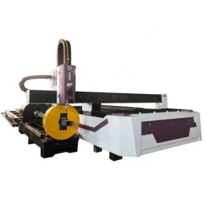
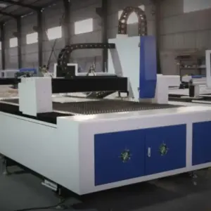
This report evaluates the deployment and operational efficacy of the 30kW Fiber Laser H-Beam Cutting Machine, specifically configured with a ±45° 5-axis beveling head. The evaluation took place within the context of the Charlotte metropolitan infrastructure expansion, focusing on the fabrication of heavy structural components for multi-span steel girder bridges.
In bridge engineering, the transition from conventional plasma cutting and mechanical drilling to high-kilowatt fiber laser technology represents a fundamental shift in metallurgical management and structural tolerance. The Charlotte projects require adherence to stringent AASHTO (American Association of State Highway and Transportation Officials) standards, necessitating a level of precision in H-beam processing that traditional methods struggle to maintain without significant secondary labor.
2.0 30kW Power Density and Material Interaction
The 30kW fiber laser source provides a power density that redefines the “thick-plate” cutting threshold for structural steel grades such as A572 Grade 50 and A709. At this power level, the laser maintains a high-intensity focal point capable of vaporizing steel thicknesses of up to 40mm-50mm with minimal assist gas pressure compared to lower-wattage systems.
2.1 Thermal Influence Zone (HAZ) Management:
In bridge engineering, the Heat Affected Zone (HAZ) is a critical variable. Excessive heat input can lead to local hardening or grain growth, potentially compromising the fatigue resistance of the H-beam. The 30kW system, by virtue of its high feed rate (m/min), significantly reduces the residence time of the beam on the material. This results in a narrower HAZ than that produced by oxy-fuel or high-definition plasma, preserving the base metal’s mechanical properties near the cut edge.
2.2 Kerf Characteristics and Surface Roughness:
The 30kW source allows for a highly stable “keyhole” welding-cutting mode. For the Charlotte bridge girders, surface roughness (Rz) of the cut edge is maintained within 15-30 microns. This eliminates the need for edge grinding prior to the application of high-performance anti-corrosion coatings, a mandatory requirement for North Carolina Department of Transportation (NCDOT) projects.
3.0 Kinematics of ±45° Bevel Cutting
The integration of a 5-axis infinite rotation head allows for the execution of complex bevels (V, Y, X, and K shapes) directly on the H-beam flanges and webs. This capability is the technical pivot point for high-efficiency bridge fabrication.
3.1 Weld Preparation Optimization:
Traditional H-beam processing requires separate stations for cutting-to-length and beveling. The ±45° bevel technology enables the machine to perform “Full Penetration” (CJP) weld preparations in a single pass. By articulating the cutting head during the flange processing, the machine creates a precise bevel angle that ensures uniform root gaps during bridge assembly.
3.2 Compensation for Structural Deviations:
H-beams, particularly those used in large-scale Charlotte bridge projects, often exhibit “mill tolerance” deviations—camber, sweep, or flange tilt. The ±45° laser system utilizes integrated laser sensors to map the beam’s actual topography in 3D space before the cut. The software then dynamically adjusts the 5-axis toolpath to ensure that the bevel angle remains constant relative to the actual surface of the steel, rather than the theoretical CAD model.
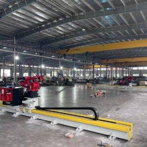
4.0 Synergy with Automated Structural Processing
The 30kW H-beam laser is not merely a cutting tool but a centralized processing hub. Its synergy with automated material handling and software integration solves several bottlenecks inherent in heavy steel fabrication.
4.1 Integrated Nesting and Bolt Hole Precision:
In bridge construction, the precision of bolt holes for splice plates is paramount. The 30kW laser achieves a diametric tolerance of ±0.1mm, significantly surpassing the ±0.5mm to ±1.0mm tolerance common in plasma or mechanical punching. By integrating the nesting software directly with Tekla or SDS/2 BIM models, the Charlotte fabrication facility can ensure that every H-beam arrives at the site with 100% alignment accuracy for field bolting.
4.2 Throughput Efficiency:
The 30kW system processes a standard 12-meter H-beam with complex web penetrations and flanged bevels in approximately 18% of the time required by traditional CNC drill lines and manual torching. This throughput is vital for meeting the aggressive timelines of Charlotte’s urban corridor bridge replacements.
5.0 Structural Integrity and Fatigue Considerations
Bridge engineering is governed by fatigue life. A primary concern with thermal cutting is the introduction of micro-fissures or striations that act as stress concentrators.
5.1 Striation Control:
The 30kW laser, when tuned with optimized frequency and pulse width modulation, produces a nearly smooth cut surface. Under 50x magnification, the “drag lines” or striations are significantly shallower than those found in 10kW or 20kW cuts. In the context of the Charlotte project’s dynamic load requirements, these smoother edges reduce the likelihood of crack initiation at the beam’s tension zones.
5.2 Dross-Free Bottom Edges:
High-power fiber lasers facilitate “dross-free” cutting on the underside of the flange. In traditional bridge fabrication, dross (re-solidified slag) must be manually chipped away, a process that often nicks the base metal. The 30kW source’s ability to maintain high melt-pool fluidity ensures that the assist gas (typically Oxygen for carbon steel or Nitrogen for stainless) effectively clears the kerf, leaving a clean bottom edge.
6.0 Technical Challenges and Mitigation
Despite the advantages, the 30kW H-beam laser requires rigorous environmental and operational controls.
6.1 Beam Delivery and Optics:
At 30,000 watts, the optical components are subject to extreme thermal loads. The use of high-grade fused silica lenses and active water-cooling cycles is mandatory. Any contamination on the protective window will result in immediate thermal shift, altering the focal point and compromising the bevel angle. The Charlotte facility has implemented a “Clean Room” protocol for lens replacement to mitigate this risk.
6.2 Reflection Management:
Cutting thick H-beams involves navigating internal corners where the laser may reflect off the web or flange. The 30kW system utilizes back-reflection sensors and specialized software algorithms that de-tune the power or adjust the feed rate when the sensor detects reflected photons, protecting the fiber source from catastrophic failure.
7.0 Conclusion
The deployment of the 30kW Fiber Laser H-Beam Cutting Machine with ±45° bevel technology has proven to be a transformative asset for bridge engineering in Charlotte. By consolidating multiple fabrication steps—length cutting, hole drilling, slotting, and weld prep—into a single automated process, the system significantly reduces the “Total Cost of Quality” (TCQ).
The metallurgical advantages of the 30kW source, specifically the minimized HAZ and superior edge finish, directly contribute to the long-term structural integrity and fatigue life of the steel girders. As bridge designs become more complex to accommodate Charlotte’s growing transit needs, the precision and articulation of 5-axis laser processing will become the baseline standard for the heavy steel industry.
Report End.
Authorized by: Lead Structural Engineer, Laser Metallurgy Division.