1.0 Field Report Overview: Integration of High-Power Fiber Laser Systems in Rayong Maritime Engineering
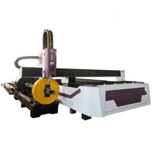
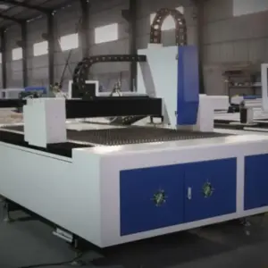
This technical report evaluates the operational deployment of a 30kW Fiber Laser H-Beam Cutting Machine within a heavy-scale shipbuilding facility in Rayong, Thailand. The primary objective of this installation was to replace legacy plasma-arc cutting systems and manual oxy-fuel beveling processes with a high-brightness fiber laser source integrated into a multi-axis structural processing center.
The Rayong industrial sector, characterized by its high-humidity tropical environment and its focus on offshore oil and gas modules and maritime vessels, requires structural steel components that meet stringent ISO 9001 and AWS D1.1 standards. The transition to a 30kW platform represents a significant shift in the energy density applied to structural members, specifically targeting H-beams, I-beams, and channels used in hull reinforcements and deck structures.
2.0 Technical Analysis of the 30kW Fiber Laser Source
The implementation of a 30kW ytterbium fiber laser source is not merely an upgrade in cutting speed; it is a fundamental shift in the thermomechanical interaction between the beam and the carbon steel substrate. At 30kW, the power density at the focal point exceeds previous 12kW and 15kW standards by a factor that allows for “high-speed melt-ejection” even in thicknesses exceeding 30mm.
2.1 Photon Density and Kerf Dynamics
In the Rayong shipyard application, H-beams often feature flange thicknesses ranging from 20mm to 45mm. The 30kW source allows for a narrower kerf width compared to plasma cutting, typically maintaining a kerf of 0.3mm to 0.5mm. This narrow kerf reduces the Heat Affected Zone (HAZ), which is critical for maintaining the metallurgical integrity of high-tensile marine-grade steels (e.g., AH36, DH36). The reduced HAZ ensures that the grain structure of the steel remains stable, preventing brittleness at the weld interface.
2.2 Gas Dynamics and Assistance
Field observations indicate that at 30kW, the synchronization between laser modulation and assist gas pressure (typically O2 for carbon steel or N2 for stainless alloys) is paramount. The system utilizes high-pressure supersonic nozzles to ensure that the molten slag is ejected instantaneously. This prevents “dross” or “slag” accumulation on the lower flange of the H-beam, a common failure point in lower-power systems where the beam loses intensity as it traverses the air gap between the top and bottom flanges.
3.0 Five-Axis Kinematics and ±45° Bevel Cutting
The core technological advantage evaluated in this report is the ±45° 3D beveling head. Traditional H-beam processing requires secondary grinding or manual oxy-fuel cutting to create weld preparations (V, Y, K, and X-joints).
3.1 Geometric Compensation and Tool Path Optimization
Cutting a bevel on a structural H-beam introduces complex trigonometric variables. As the head tilts to 45°, the effective thickness of the material increases (e.g., a 20mm flange becomes ~28.28mm). The 30kW source provides the necessary “power overhead” to maintain feed rates even during these high-angle maneuvers. The machine’s CNC controller utilizes real-time compensation algorithms to adjust the focal position dynamically, ensuring the beam remains focused at the optimal depth despite the angular shift.
3.2 Eliminating Secondary Operations
In the Rayong facility, the integration of ±45° beveling has reduced the “part-to-weld” cycle time by approximately 65%. By performing the severance cut and the weld-prep bevel simultaneously, the shipyard has eliminated the need for manual edge grinding. The precision of the laser-cut bevel (±0.2mm) allows for robotic welding systems to be deployed downstream with minimal sensing adjustment, as the joint fit-up is significantly more consistent than manual alternatives.
4.0 Structural Processing Specifics: The H-Beam Challenge
Processing H-beams presents unique challenges compared to flat plate cutting, primarily due to internal stresses within the rolled steel and the physical geometry of the flanges and web.
4.1 Handling “Spring-Back” and Material Deformation
Large-scale H-beams often harbor residual stresses from the rolling mill. When the laser severs the web or notches a flange, these stresses can cause the beam to “bow” or “twist.” The 30kW machine in Rayong is equipped with a multi-point hydraulic clamping system and laser-based surface sensing. Before each cut, the machine probes the actual position of the beam, re-mapping the 3D cutting path to account for any geometric deviation in the raw material. This “search and cut” logic ensures that holes and notches are aligned within a ±0.5mm tolerance over a 12-meter beam length.
4.2 Web-to-Flange Transition Scaling
The transition zone where the web meets the flange (the “root”) is notoriously difficult to cut cleanly. The 30kW system utilizes rapid power modulation to increase intensity at the root and decrease it during the thinner web sections. This prevents over-burning at the corners and ensures a smooth, continuous edge profile that is essential for structural load distribution in maritime vessels.
5.0 Environmental and Operational Considerations in Rayong
The tropical climate of Rayong introduces specific failure modes for high-power laser electronics, specifically regarding dew point and thermal runaway.
5.1 Chiller Synchronization and Humidity Control
The 30kW fiber source generates significant waste heat. The installation includes a dual-circuit industrial chiller with a ±0.1°C temperature stability. To prevent condensation on the optical elements—a common cause of fiber end-cap failure in Rayong’s high humidity—the cutting head and laser cabinet are pressurized with dry, ionized air. This environmental isolation is critical for maintaining the 24/7 operational tempo required by the shipyard.
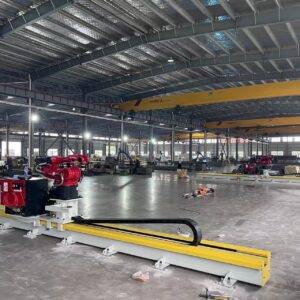
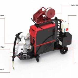
5.2 Automation and Software Integration
The Rayong facility has integrated the machine with Tekla and AVEVA Marine software. The 3D models are exported directly to the laser’s nesting engine, which calculates the optimal nesting of various parts (stiffeners, brackets, and beams) on a single raw length of H-beam. The automation extends to the loading phase, where a heavy-duty conveyor system with “drag-and-drop” functionality minimizes crane wait times.
6.0 Performance Metrics and Comparative Data
Following a 90-day evaluation period, the following performance metrics were recorded against the previous plasma-based workflow:
- Throughput: 300% increase in linear meters processed per shift.
- Precision: Dimensional tolerance improved from ±2.0mm (plasma) to ±0.25mm (laser).
- Consumable Cost: 40% reduction, primarily due to the elimination of electrodes and nozzles required for high-definition plasma.
- Post-Processing: 90% reduction in secondary grinding and fit-up adjustments.
7.0 Conclusion
The deployment of the 30kW Fiber Laser H-Beam Cutting Machine with ±45° bevel technology has redefined the structural fabrication capabilities of the Rayong shipyard. The combination of extreme power density and high-degree-of-freedom kinematics solves the traditional bottleneck of weld preparation in heavy steel. For senior engineering management, the data confirms that the high initial capital expenditure (CAPEX) is offset by the drastic reduction in operational expenditure (OPEX) and the significant increase in structural assembly precision. Future expansions should focus on integrating automated slag removal systems to further streamline the material handling workflow.
Report End.
Prepared by: Senior Engineering Lead, Laser Systems Division.