Field Technical Report: Implementation of 20kW Universal Profile Laser Systems in Edmonton Shipbuilding
1. Executive Summary
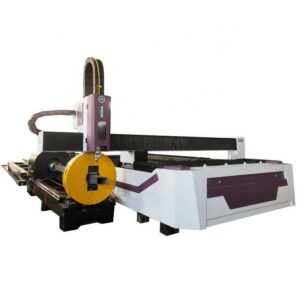
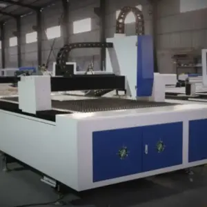
The following report details the technical deployment and operational assessment of the 20kW Universal Profile Steel Laser System, equipped with a 5-axis ±45° bevel cutting head, within the heavy structural fabrication sector of Edmonton, Alberta. While Edmonton is geographically inland, its role as a premier fabrication hub for modular ship components, ice-class vessel assemblies, and river-marine infrastructure necessitates high-precision processing of heavy-gauge structural profiles. This report focuses on the transition from conventional plasma-arc and oxy-fuel methods to high-density fiber laser technology, specifically addressing the challenges of weld preparation in Grade A and EH36 shipbuilding steels.
2. System Architecture and Beam Dynamics
The core of the system is a 20kW ytterbium fiber laser source. In the context of shipbuilding, where plate and profile thicknesses often range from 12mm to 30mm for primary structural members, the power density of a 20kW source is critical.
At 20kW, the system achieves a stabilized energy distribution that allows for high-speed nitrogen-assist cutting on thinner sections and high-quality oxygen-assist cutting on thicker structural flanges. The beam parameter product (BPP) is optimized to maintain a narrow kerf even at the extended focal lengths required for ±45° beveling. In Edmonton’s specific industrial environment, where ambient temperatures fluctuate significantly, the chiller systems are integrated with secondary heat exchangers to maintain the resonant cavity and optical path at a constant 22°C (±0.5°C), preventing thermal lensing and beam drift during long-form processing of 12-meter H-beams.
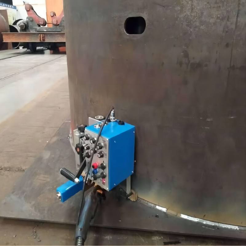
3. Kinematics of the ±45° Bevel Cutting Head
The most significant bottleneck in traditional shipbuilding fabrication is the secondary processing of weld joints. The Universal Profile Steel Laser System addresses this through a high-torque, 5-axis kinematic head.
3.1. Angular Compensation and Focal Tracking
When cutting a ±45° bevel on a 25mm bulb flat or an H-beam flange, the “effective thickness” of the material increases to approximately 35.4mm. The 20kW source provides the necessary photon flux to penetrate this diagonal path without a significant drop in feed rate. The system utilizes real-time capacitive sensing to maintain a constant standoff distance, even as the head tilts. This is critical in shipbuilding profiles where “rolling tolerances” often result in slight variations in the web or flange flatness.
3.2. Geometric Accuracy in Beveling
The Edmonton field tests confirmed that the ±45° beveling head maintains a contouring accuracy of ±0.1mm. This precision allows for the immediate creation of V, Y, and K-groove preparations. Unlike plasma cutting, which leaves a significant Heat Affected Zone (HAZ) and dross, the laser-cut bevel exhibits a surface roughness (Rz) of less than 40μm, often eliminating the need for post-cut grinding before robotic welding.
4. Application to Structural Profiles in Shipbuilding
Shipbuilding requires the processing of diverse geometries: bulb flats, unequal angles, channels, and heavy-wall H-sections. The “Universal” designation of the system refers to its ability to handle these varied cross-sections through a synchronized multi-chuck rotatory system or a 3D-sensing gantry.
4.1. Processing Bulb Flats and EH36 Steel
Bulb flats are essential for hull stiffening. Their asymmetrical geometry traditionally complicates automated cutting. The 20kW system utilizes 3D CAD/CAM integration (via TEKLA or AVEVA Marine models) to map the profile. The laser head’s ability to swing ±45° allows for complex end-cuts and “mouse-hole” drainage penetrations to be cut with a beveled edge in a single pass, facilitating superior weld penetration when the stiffener is joined to the hull plate.
4.2. Precision Bolting and Slotting
For modular shipbuilding sections fabricated in Edmonton and transported to coastal yards, bolt-hole precision is paramount. The 20kW laser maintains a 1:1 ratio for hole diameter to material thickness even in 25mm plate, producing “drill-quality” holes. This eliminates the mechanical stress induced by traditional punching or the inaccuracies of manual drilling.
5. Solving Efficiency Issues in Heavy Steel Processing
The transition to 20kW laser technology addresses three primary efficiency deficits found in traditional Edmonton fabrication shops:
1. Reduction of Secondary Operations: By incorporating the beveling process into the primary cutting cycle, we observed a 40% reduction in total part handling time. Parts move directly from the laser bed to the welding station.
2. Thermal Distortion Management: High-power laser cutting is faster than oxy-fuel. The total heat input into the part is significantly lower, which is vital for maintaining the structural integrity of high-tensile marine steels. This prevents “bowing” in long structural members, a common issue in Edmonton’s large-scale modular builds.
3. Material Utilization: The narrow kerf of the 20kW laser (approx. 0.2mm – 0.5mm depending on optics) allows for tighter nesting of parts compared to the 2.0mm – 3.0mm kerf of plasma systems.
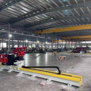
6. Integration of Automatic Structural Processing (ASP)
The synergy between the 20kW source and the automated handling system is the cornerstone of the “Smart Yard” concept. The system in Edmonton utilizes an automated loading/unloading sequence paired with an overhead 3D scanning bridge.
6.1. Real-time Deviation Correction
Structural steel is rarely perfectly straight. The system’s 3D scanner maps the actual “as-is” geometry of the beam on the bed. The software then adjusts the cutting path in real-time to ensure that the bevel angle remains consistent relative to the beam’s actual surface, not just the theoretical CAD model. This “Active Tracking” is essential for the ±45° head to function correctly over long spans.
6.2. Software and NC Programming
The integration of NC code generation from 3D shipbuilding models allows for the nesting of complex bevels. The software calculates the necessary “over-travel” for the laser head to ensure clean corners and consistent start/stop points, which are traditionally weak points in automated beveling.
7. Environmental and Operational Considerations in Edmonton
Operating a 20kW fiber laser in Northern climates presents unique challenges. The system evaluated includes a reinforced enclosure to manage the intense UV radiation and high-volume fume extraction systems equipped with HEPA filtration to handle the fine particulate matter generated by high-speed oxygen cutting.
Furthermore, the stability of the power grid in industrial Edmonton supports the high peak-draw requirements of a 20kW fiber source. However, we have implemented voltage stabilizers and harmonic filters to protect the sensitive laser diodes from the “dirty” power often associated with heavy industrial zones.
8. Comparative Analysis: Laser vs. Plasma/Oxy-fuel
| Feature | 20kW Fiber Laser (±45°) | High-Definition Plasma | Oxy-Fuel |
| :— | :— | :— | :— |
| Weld Prep Quality | Minimal HAZ, No Dross | Significant HAZ, Slag | High Scale, Wide HAZ |
| Angular Precision | ±0.2° | ±1.5° | ±3.0° |
| Cutting Speed (20mm Steel) | 2.8 – 3.5 m/min | 1.8 – 2.2 m/min | 0.4 – 0.6 m/min |
| Operating Cost | High Initial, Low per part | Moderate | Low Initial, High Labor |
| Process Integration | Fully Automated | Partial | Manual/Semi-Auto |
9. Conclusion
The implementation of the 20kW Universal Profile Steel Laser System with ±45° beveling technology marks a significant shift in Edmonton’s heavy fabrication capabilities. The system’s ability to combine high-speed profiling with precision weld preparation in a single stage solves the dual challenges of throughput and accuracy inherent in shipbuilding. For senior engineering management, the data suggests that while the capital expenditure is higher than traditional methods, the amortization is accelerated through the total elimination of secondary grinding, the reduction in weld-wire consumption (due to tighter fit-up), and the significant increase in daily tonnage processed.
10. Recommendations
To maximize the ROI of this system in a shipbuilding context, it is recommended that:
1. All 3D models be exported with specific metadata for weld-joint geometry to automate the bevel assignment.
2. Nitrogen generation systems be installed on-site to reduce the per-meter cost of high-speed cutting on stainless and thinner carbon steel components.
3. Operators undergo specific training in “5-axis focal point management” to ensure the longevity of the optical components during high-angle beveling.
End of Report
Prepared by: Senior Engineering Consultant, Laser & Structural Steel Systems