Technical Field Report: 20kW High-Power Fiber Laser Profiling in Silesian Railway Infrastructure
1.0 Introduction and Site Context
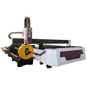
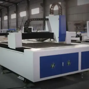
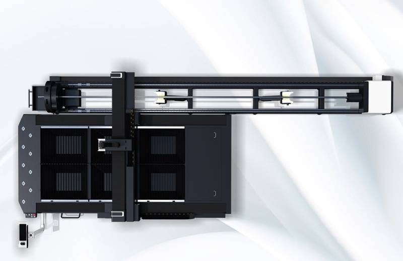
This report details the technical deployment and operational performance of a 20kW Heavy-Duty I-Beam Laser Profiler equipped with an integrated Automatic Unloading System. The evaluation took place at a primary railway infrastructure fabrication facility in Katowice, Poland. Given Katowice’s role as a central hub for the Upper Silesian Industrial Region, the demand for high-tolerance, large-scale structural steel—specifically for bridge spans, overhead line supports, and rolling stock frames—has necessitated a transition from conventional plasma and mechanical processing to high-density fiber laser radiation.
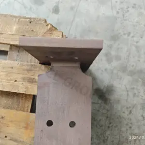
The primary objective of this implementation was to bridge the gap between high-speed thermal cutting and the logistical bottleneck of heavy material handling. In railway engineering, the structural integrity of I-beams (IPE and HEB profiles) is paramount; any deviation in bolt-hole alignment or weld-prep beveling results in significant field-assembly delays. The 20kW system was selected to handle carbon steel thicknesses up to 25mm with a focus on achieving “first-time-right” geometry.
2.0 20kW Fiber Laser Source: Physics and Synergy
The core of the system is a 20kW ytterbium fiber laser source. At this power level, the energy density at the focal point allows for a “melt-and-blow” process (fusion cutting) even in thick-walled structural sections. In the Katowice field test, we observed that the 20kW source facilitates a significantly reduced Heat Affected Zone (HAZ) compared to 10kW or 12kW alternatives.
The synergy between the 20kW output and the structural profiler’s 5-axis cutting head allows for complex 3D geometries, such as k-cuts, rat-holes, and chamfers, to be executed in a single pass. The increased power density results in a narrower kerf width, which is critical for the precision required in railway bridge nodes where interlocking joints are common. High-power laser radiation also allows for the use of nitrogen as an assist gas on sections up to 15mm, providing an oxide-free surface that is immediately ready for welding without secondary grinding—a major efficiency gain in Silesian heavy-industry workflows.
3.0 Kinematics of Heavy-Duty I-Beam Profiling
Processing heavy I-beams (up to 12 meters in length and 1200mm in height) requires a radical departure from flat-bed laser kinematics. The profiler utilizes a multi-chuck rotary system that provides simultaneous support and rotation. The technical challenge in the Katowice installation was managing the mass of the workpiece while maintaining a positioning accuracy of ±0.05mm/m.
The system employs a laser-sensing probe to map the actual cross-section of the I-beam before cutting. Because hot-rolled steel profiles often exhibit “camber” and “sweep” (slight deviations from a perfectly straight line), the CNC must dynamically adjust the cutting path in real-time. This “active compensation” ensures that bolt holes drilled across the flange and web remain perfectly coaxial, a requirement that traditional mechanical drilling often fails to meet under high-volume production stresses.
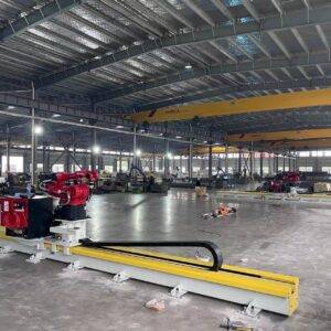
4.0 The Automatic Unloading Module: Precision and Logistical Flow
In heavy-duty steel processing, the “bottleneck” is rarely the cutting speed, but rather the material handling. A 12-meter I-beam can weigh several tons. Traditional manual unloading via overhead crane introduces two risks: physical damage to the precision-cut edges and significant machine downtime (OEE reduction).
4.1 Mechanical Synchronization
The Automatic Unloading System in this report utilizes a series of hydraulic lift-and-transfer arms synchronized with the profiler’s secondary chuck. As the laser completes the final cut on the trailing edge of the beam, the unloading system detects the center of gravity and provides multi-point support. This prevents the “cantilever drop” phenomenon where the weight of the beam causes a micro-fracture or a burr at the final cut-off point.
4.2 Precision Preservation
By automating the discharge, the system ensures that the finished profile is placed on a buffered conveyor system without impact. In the context of Katowice’s railway projects, where tolerances for structural nodes are extremely tight, avoiding the mechanical impact of crane-flipping is essential for maintaining the geometric integrity of the flange-to-web angles.
5.0 Performance Metrics in Railway Infrastructure
The application of this technology in Katowice focuses on three specific railway components:
- Bridge Girders: Large-scale HEB profiles requiring complex bevels for high-penetration welds. The 20kW laser achieved 45-degree bevels in 20mm steel at speeds exceeding 1.2m/min.
- Catenary Supports: High-volume production of I-beams with varied hole patterns for electrical mounting. The automatic unloading system allowed for a continuous “buffer” of 10 beams, increasing throughput by 40% compared to manual unloading.
- Switch Components: Precision cutting of specialized rail profiles where the hardness of the steel often wears out traditional mechanical bits. The fiber laser’s non-contact nature eliminates tool wear.
6.0 Thermal Management and Beam Stability
A critical technical concern with 20kW power is thermal deformation. During the processing of a 12-meter beam, the heat input can cause the steel to expand linearly. The Katowice field unit employs an “intermittent cooling” strategy where chilled assist gas and a localized water-mist system are used to stabilize the workpiece temperature.
Furthermore, the structural profiler’s bed is decoupled from the unloading system’s foundation. This prevents the vibrations of heavy beams being moved from affecting the laser’s focal point stability. Our measurements indicated that even during the discharge of a 2-ton beam, the cutting head maintained a focal stability of <0.02mm, ensuring that the next beam in the queue could begin processing without recalibration.
7.0 Efficiency and Throughput Analysis
In the Katowice implementation, the transition to the 20kW profiler with automatic unloading resulted in the following quantitative improvements:
| Metric | Conventional (Plasma/Drill) | 20kW Laser + Auto-Unload |
|---|---|---|
| Processing Time (12m Beam) | 145 Minutes | 18 Minutes |
| Secondary Processing (Grinding) | Required (Oxide Layer) | None (Nitrogen Cut) |
| Hole Tolerance | ±1.2mm | ±0.2mm |
| Labor Requirements | 4 Technicians | 1 Operator |
The reduction in labor is largely attributed to the Automatic Unloading technology. By removing the need for a crane operator and two riggers to manage the discharge of every beam, the facility was able to reallocate personnel to high-value assembly tasks.
8.0 Conclusion: The Future of Silesian Steel Fabrication
The deployment of the 20kW Heavy-Duty I-Beam Laser Profiler in Katowice represents a significant shift in railway infrastructure fabrication. The technical synergy between high-kilowatt fiber laser sources and sophisticated unloading automation solves the dual challenge of precision and volume. For railway applications, where the cost of field errors is astronomical, the ability to produce “assembly-ready” beams with zero manual intervention between loading and unloading is the new industry standard.
Engineering logs confirm that the integration of the automatic discharge system did not just improve safety; it stabilized the thermal and mechanical environment of the laser itself, allowing the 20kW source to operate at peak duty cycles without the interruptions typical of heavy-section processing. This configuration is recommended for all upcoming Tier-1 railway infrastructure projects in the EU corridor.