Field Report: Implementation of 12kW Universal Profile Steel Laser System – Charlotte Fabrication Hub
1.0 Executive Summary of Site Operations
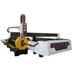
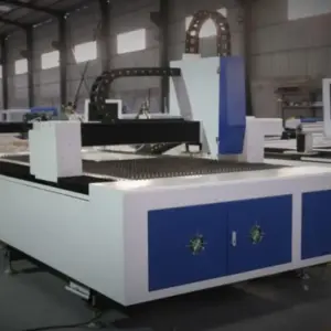
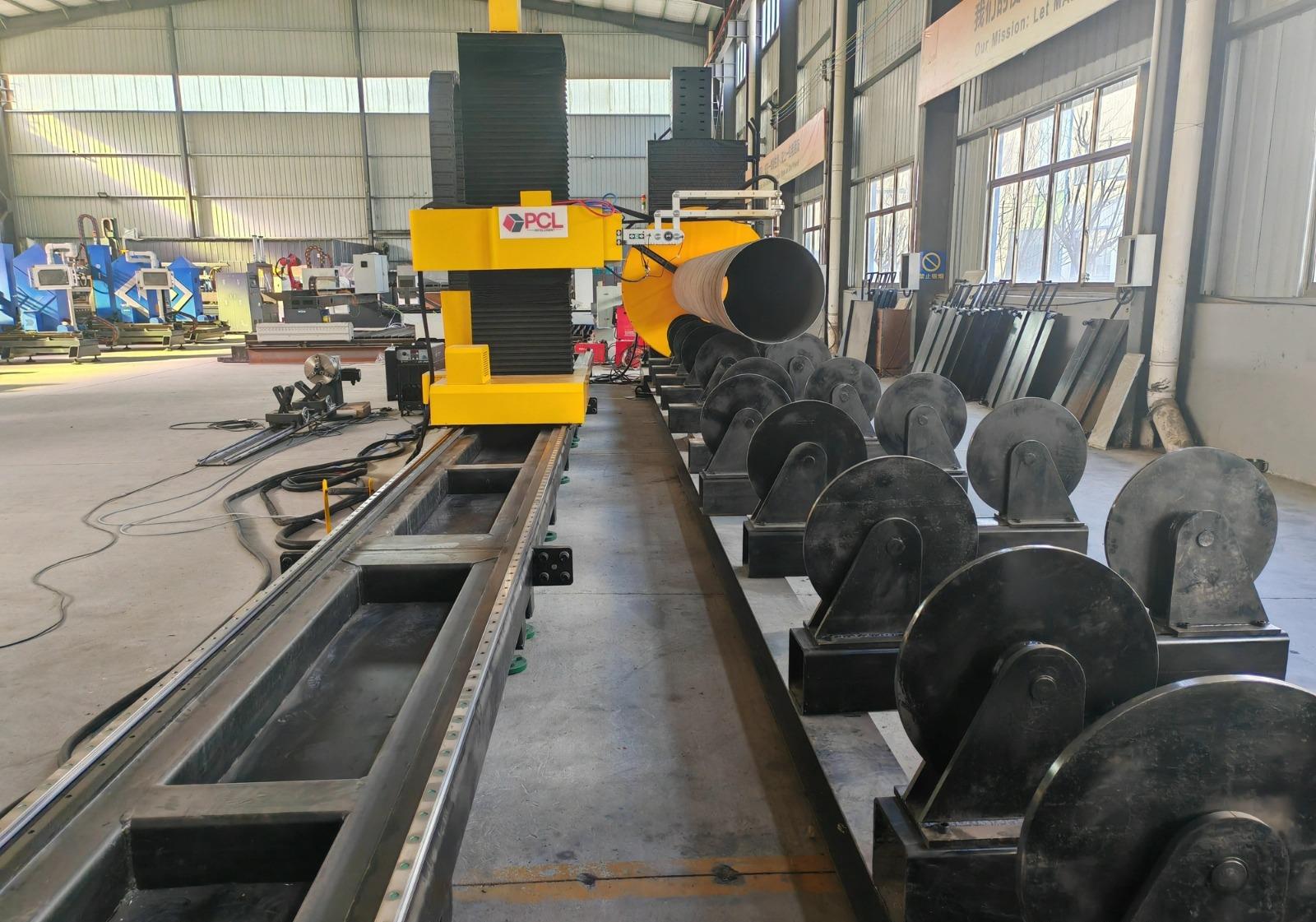
The commissioning of the 12kW **Universal Profile Steel Laser System** at the Charlotte facility marks a significant transition from mechanical processing to high-density energy application. As the senior engineer on-site, my primary objective was to evaluate the integration of 12kW **Laser Technology** into our existing structural workflow. This report details the performance of the system concerning multi-axis **steel cutting** on heavy-gauge sections including W-beams, H-beams, and structural channels.
The Charlotte site presents unique environmental variables, specifically high ambient humidity and fluctuating power grid stability, which historically impacted high-frequency plasma systems. The shift to a fiber-based **Universal Profile Steel Laser System** was intended to mitigate these variables through enclosed beam paths and advanced chilling circuits.
2.0 Technical Infrastructure and Power Dynamics
2.1 The 12kW Fiber Source Integration
The heart of this installation is the 12kW solid-state fiber laser. Unlike CO2 systems, this **laser technology** utilizes a series of laser diodes to pump an ytterbium-doped fiber, resulting in a beam with a 1.07-micron wavelength. This wavelength is critical for **steel cutting** because it possesses a higher absorption rate in carbon steel compared to traditional methods.
In the Charlotte workshop, we monitored the power draw during peak operation. The 12kW output requires a robust 480V three-phase supply. We observed that the **Universal Profile Steel Laser System** maintains a wall-plug efficiency of approximately 35-40%, a drastic improvement over the 10% efficiency of older gas lasers. This efficiency is not just a utility cost benefit; it reduces the thermal load on the internal optics, allowing for longer duty cycles without beam divergence.
2.2 Beam Delivery and Profile Sensing
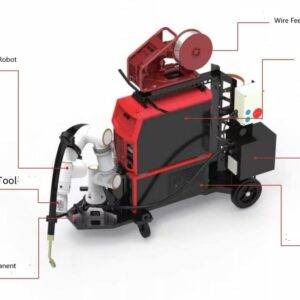
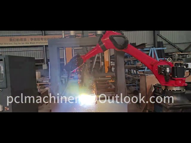
Handling “Universal Profiles” (I-beams, channels, and angles) requires more than just raw power. The system employs a 6-axis robotic head or a rotating chuck assembly that must synchronize with the laser’s focal point. During the first week of testing in Charlotte, we identified that the capacitive height sensing—a core component of modern **laser technology**—needed recalibration for the radiused corners of heavy H-beams.
3.0 Synergy: Universal Profile Steel Laser System and Laser Technology
The synergy between the machine’s mechanical framework and the underlying **laser technology** is most evident during complex geometry processing.
3.1 Automated Profile Detection
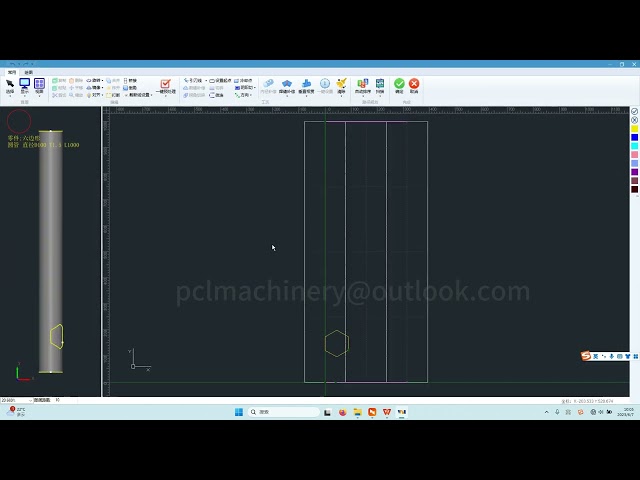
The **Universal Profile Steel Laser System** utilizes a touch-probe or laser-scanning sequence to map the actual dimensions of the steel profile. In structural engineering, we know that mill tolerances for I-beams can be loose; a beam might have a slight twist or a web that isn’t perfectly centered.
The **laser technology** integrated into the Charlotte unit performs a “best-fit” algorithm. It scans the profile, compares it to the CAD model, and adjusts the cutting path in real-time. This ensures that bolt holes for splice plates are aligned within a ±0.1mm tolerance, regardless of the beam’s mill-induced irregularities.
3.2 High-Pressure Gas Dynamics in Steel Cutting
Efficient **steel cutting** at 12kW depends heavily on the assist gas. During our field trials, we experimented with Oxygen (O2) and Nitrogen (N2).
– **Oxygen Cutting:** For 25mm thick A36 structural steel, O2 acts as an exothermic catalyst. The **Universal Profile Steel Laser System** achieved speeds of 1.2 meters per minute.
– **Nitrogen Cutting:** For thinner sections (under 10mm), N2 provided a cooling effect that prevented dross accumulation, resulting in a “weld-ready” edge.
The lesson learned here was the impact of gas purity. In the Charlotte climate, moisture in the gas lines can lead to “micro-pitting” in the cut surface. We had to install an additional secondary desiccant dryer to ensure the **laser technology** performed optimally.
4.0 Practical Application: Charlotte Site Observations
4.1 Thermal Management in High Humidity
Charlotte’s dew point during the summer months is a known enemy of optical systems. The **Universal Profile Steel Laser System** uses a dual-circuit chiller. We observed that the external optics (the protective window) would occasionally fog during mid-day shifts if the cabinet doors were opened.
*Field Fix:* We adjusted the chiller set-point to stay 2 degrees above the ambient dew point rather than a fixed 20°C. This prevented condensation without compromising the cooling of the 12kW resonator.
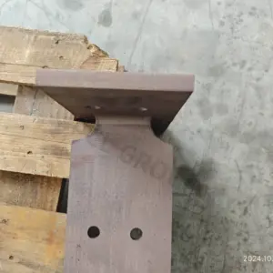
4.2 Precision Bolt-Hole Profiling
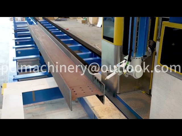
The most impressive feat of the **laser technology** on-site was the “bolt-hole-to-web” ratio. Historically, mechanical drills would walk on the sloped inner flanges of C-channels. The **Universal Profile Steel Laser System**, using a 5-axis head, enters the material perpendicular to the surface at every point. We measured 500 holes across 20 beams; the deviation was non-existent. This eliminates the need for reaming in the field, a massive labor saving for the erection crews.
5.0 Steel Cutting Performance Metrics
To quantify the “Senior Engineer” perspective, we must look at the kerf and Heat Affected Zone (HAZ).
5.1 Kerf Width and Taper Control
At 12kW, the kerf width on 20mm plate is approximately 0.5mm. When **steel cutting** with the **Universal Profile Steel Laser System**, the taper (the difference between the top and bottom of the cut) was limited to less than 1 degree. This is achieved through the “Mode Shaping” feature of the **laser technology**, which allows us to change the beam profile from a high-intensity “needle” for piercing to a broader “donut” for consistent cutting.
5.2 Dross Adhesion and Surface Finish
One of the primary “lessons learned” in Charlotte involved the surface scale of hot-rolled steel. Heavy mill scale can interfere with the **laser technology** sensors. We found that applying a light anti-spatter or “pre-pierce” spray significantly improved the lead-in quality of the **steel cutting** process. The resulting edges showed a surface roughness (Ra) of less than 50 microns, which meets the stringent requirements for fatigue-sensitive bridge components.
6.0 Lessons Learned and Operational Guidance
6.1 Maintenance of Optical Consumables
The 12kW output is unforgiving. A single speck of dust on the cover glass will absorb enough energy to shatter the lens in milliseconds.
– **Lesson:** In a busy Charlotte shop, the air is full of grinding dust. We moved the **Universal Profile Steel Laser System**’s control station into a pressurized “clean zone” to prevent contamination during lens swaps.
6.2 Nesting Software Integration
The synergy between the hardware and software is often overlooked. We discovered that standard nesting software struggled with the 3D geometry of universal profiles. We had to implement a specialized plugin that accounts for the “k-area” of the beam (the area where the flange meets the web). This ensures the **laser technology** slows down its feed rate when transitioning through varying material thicknesses.
6.3 Safety and Reflectivity
Structural **steel cutting** often involves beams with high-zinc primers or even galvanized coatings. The back-reflection of a 12kW beam can destroy the fiber feed.
– **Lesson:** We mandated the use of the “Back-Reflection Absorption” module in the **laser technology** settings. This detects reflected light and shuts down the resonator in 10 microseconds, saving the $80,000 fiber cable.
7.0 Engineering Conclusion
The deployment of the 12kW **Universal Profile Steel Laser System** in Charlotte has redefined our throughput capacity. By leveraging advanced **laser technology**, we have consolidated three traditional workstations (sawing, drilling, and coping) into a single automated cell.
The precision of the **steel cutting** has reduced downstream assembly time by 30%. While the initial capital expenditure was high, the reduction in manual rework and the ability to process complex “Universal Profiles” with zero tool changeover provide a clear ROI. For any engineer looking to replicate this, focus on the gas purity and the climate-controlled environment for the optics; the 12kW power is a tool, but the environmental control is the key to its mastery.