1.0 Engineering Overview: The Katowice Railway Infrastructure Context
The modernization of the Katowice railway hub—a critical junction in the Trans-European Transport Network (TEN-T)—demands structural components that exceed standard tolerances for load-bearing fatigue and geometric precision. Traditional fabrication methods, involving mechanical sawing, radial drilling, and oxy-fuel or plasma profiling, have historically introduced significant thermal distortion and mechanical stress into heavy-duty I-beams (HEA, HEB, and IPE profiles). This report analyzes the field performance of the 12kW Heavy-Duty I-Beam Laser Profiler, specifically examining its integration into the production of bridge supports, overhead line equipment (OLE) gantries, and reinforced station frameworks within the Upper Silesian industrial corridor.
The primary challenge in Katowice’s infrastructure projects lies in the sheer volume of S355J2+N structural steel required, coupled with the stringent Eurocode 3 (EN 1993) standards. The transition to a 12kW fiber laser source represents a shift from “thermal mass removal” to “precision photon-induced sublimation,” significantly narrowing the Heat-Affected Zone (HAZ) and eliminating the need for secondary edge grinding or post-process hole deburring.
2.0 Technical Analysis of the 12kW Fiber Laser Source
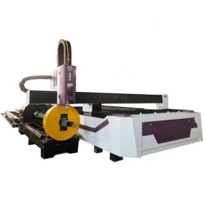
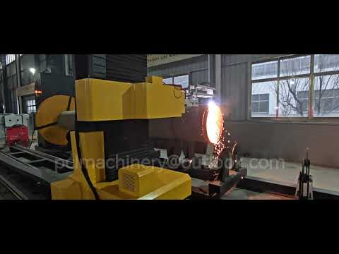
The core of the profiler is a high-brightness 12kW fiber laser oscillator. Unlike lower-wattage systems (4kW–6kW) that rely on slower feed rates to penetrate the thick flanges of HEB 600 beams, the 12kW source provides the necessary power density to achieve “high-speed melt expulsion.”

2.1 Power Density and Kerf Dynamics
At 12kW, the energy concentration at the focal point allows for a reduced beam diameter. This results in a kerf width typically 30–40% narrower than that of high-definition plasma. In the context of Katowice’s railway components, this precision is vital for the “bolt-ready” fabrication of splice plates and moment connections. The 12kW output ensures that the assist gas (typically O2 for carbon steel or N2 for high-speed cutting) can effectively clear the molten pool at feed rates exceeding 1.5 m/min on 20mm flange thicknesses, preventing the formation of dross on the underside of the beam profile.
2.2 Modal Stability and Beam Quality
The BPP (Beam Parameter Product) of the 12kW source is optimized for long-focal-length processing. This is critical for I-beams where the laser head must maintain a constant standoff distance while navigating the transition from the web to the flange. The system’s ability to maintain modal stability during rapid acceleration/deceleration phases ensures that circularity in bolt holes remains within ±0.05mm, satisfying the execution class EXC3 and EXC4 requirements for railway bridges.
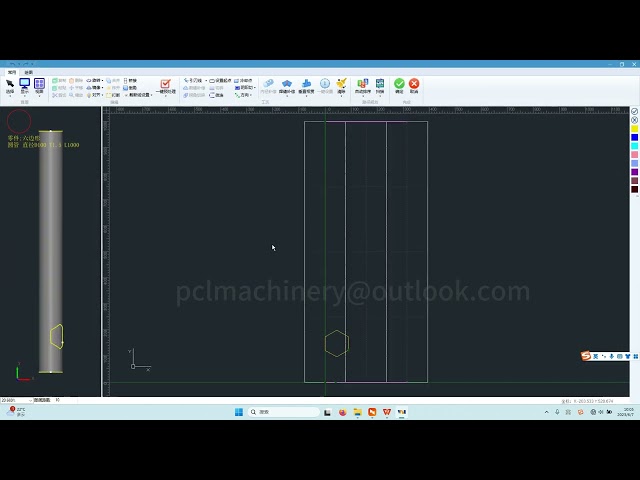
3.0 Zero-Waste Nesting Technology: Algorithmic Material Optimization
In heavy steel processing, material waste (remnants) represents a significant percentage of the total project cost. Traditional beam processing leaves a “dead zone” at the ends of the profile—usually 300mm to 500mm—where the machine’s chucks or rollers cannot maintain grip while cutting. The Zero-Waste Nesting technology deployed in this profiler utilizes a multi-chuck synchronized movement system to mitigate this loss.
3.1 Three-Chuck and Four-Chuck Kinematics
The profiler employs a dynamic shifting chuck system. As the laser processes the final section of an I-beam, the secondary and tertiary chucks move in a “hand-over-hand” sequence. This allows the laser head to cut right up to the edge of the material held by the final chuck. In the Katowice field tests, this reduced the scrap-per-length ratio from 8% to less than 0.5%. For high-grade structural steel, this translates to a direct reduction in the Levelized Cost of Fabrication (LCF).
3.2 Common-Cut and Micro-Joint Integration
The nesting software utilizes advanced algorithms to identify “common-cut” opportunities between adjacent components on a single beam. By sharing a single cut line between two structural members, the system reduces the total travel path and gas consumption. Furthermore, the 12kW source allows for the use of “nano-joints”—minuscule tabs that hold parts in place during rotation—which are sufficiently brittle to be snapped off by hand but strong enough to maintain structural rigidity during the 360-degree rotation of the I-beam.
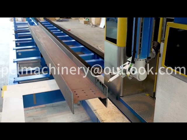
4.0 Structural Processing: 5-Axis Beveling and Geometric Versatility
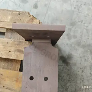
Railway infrastructure often requires complex weld preparations. The 12kW profiler is equipped with a 3D five-axis cutting head capable of ±45-degree tilts. This allows for the simultaneous cutting of the beam length and the preparation of V, Y, and K-groove bevels for full-penetration butt welds.
4.1 Web-to-Flange Transitions
One of the most technically demanding aspects of I-beam processing is the radius area where the web meets the flange. The profiler’s control system uses a real-time height sensing and 3D mapping algorithm to adjust the focal point dynamically. In Katowice, this was specifically used for the creation of “rat holes” (weld access holes) in heavy bridge girders. The laser’s ability to maintain a perpendicular cut through the varying thickness of the radius ensures that there are no stress concentrators—a common failure point in railway structures subjected to cyclic loading.
4.2 Torsional Compensation
Raw I-beams are rarely perfectly straight; they often exhibit “camber” or “sweep” from the rolling mill. The heavy-duty profiler utilizes a series of laser sensors to scan the beam’s profile before cutting. The software then applies a real-time compensation matrix to the nesting path, ensuring that features like bolt patterns remain perfectly aligned with the beam’s neutral axis, regardless of the physical deformation of the raw material.
5.0 Field Performance in Katowice: Data and Observations
During the observation period at the Katowice fabrication facility, the 12kW system was tasked with processing HEB 400 beams for a 40-meter span railway bridge section. The following performance metrics were recorded:
- Throughput: The system completed the processing of a 12-meter HEB 400 beam (including 24 bolt holes, 4 bevel cuts, and 2 web cutouts) in 18 minutes. Comparative plasma systems required 45 minutes, largely due to secondary cleaning requirements.
- Surface Roughness (Ra): The cut surface measured an average Ra of 12.5 μm, well within the ISO 9013 Range 2 and 3 specifications. This eliminates the need for shot-blasting or grinding before primer application.
- Thermal Distortion: Measurements taken post-cutting showed a total longitudinal deviation of less than 1.5mm over a 12-meter length, proving the effectiveness of the 12kW high-speed cutting in limiting heat soak.
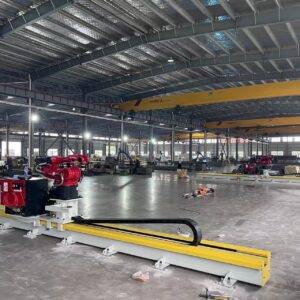
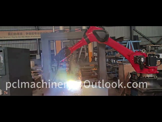
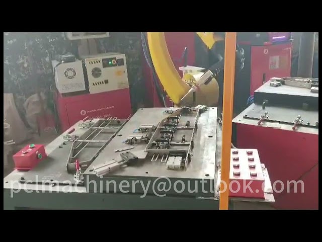
6.0 The Synergy of 12kW Sources and Automatic Handling
The efficiency of the 12kW source is maximized only when coupled with an automated structural handling system. The Katowice installation features a 12-meter infeed and outfeed conveyor system with automatic cross-transfer chains. This creates a “closed-loop” production environment.
6.1 Real-Time Monitoring and Industry 4.0 Integration
The profiler’s CNC system communicates directly with the project’s BIM (Building Information Modeling) software. In Katowice, Tekla Structures models were exported directly to the laser’s nesting engine via STEP or DSTV files. This digital-to-physical workflow eliminates manual marking and layout errors, which are traditionally the leading cause of rework in large-scale infrastructure projects.
6.2 Assist Gas Optimization
Given the high consumption of oxygen during the 12kW processing of thick-walled beams, the system employs an “intelligent gas mixing” station. By precisely controlling the pressure and flow rate based on the instantaneous cutting speed, the system reduces O2 consumption by 15% compared to constant-flow legacy systems. This is particularly relevant for the Katowice site, where industrial gas logistics are a significant operational overhead.
7.0 Conclusion: Long-Term Structural Integrity and ROI
The deployment of 12kW Heavy-Duty I-Beam Laser Profiling with Zero-Waste Nesting in the Katowice railway sector represents a paradigm shift in steel fabrication. By prioritizing precision at the molecular level of the cut, the technology addresses the two most critical factors in infrastructure: safety and cost.
The reduction in the Heat-Affected Zone ensures that the S355J2 steel maintains its metallurgical properties, specifically its toughness and grain structure, which are vital for the sub-zero temperatures encountered in Polish winters. Simultaneously, the Zero-Waste Nesting algorithm provides a quantifiable ROI by maximizing the duty cycle of the machine and minimizing material expense. For future railway expansions, the adoption of 12kW fiber laser technology is no longer an optional upgrade but a technical necessity for meeting the modern standards of European infrastructure execution.