Field Technical Report: Integration of 12kW CNC Structural Laser Systems in Wind Energy Infrastructure
1.0 Executive Overview of Deployment
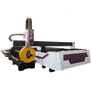
This technical report summarizes the field performance and operational integration of a 12kW CNC Beam and Channel Laser Cutter equipped with a five-axis ±45° bevel head. The deployment site is a high-capacity structural steel fabrication facility located in Charlotte, North Carolina, specifically dedicated to the production of internal structural components for wind turbine towers.
In the context of Charlotte’s growing status as a renewable energy engineering hub, the transition from traditional plasma or mechanical edge preparation to 12kW fiber laser technology represents a critical shift. The primary objective of this deployment was to eliminate secondary grinding processes and improve the fatigue life of welded joints in H-beams (HEA/HEB) and C-channels through high-precision thermal cutting.
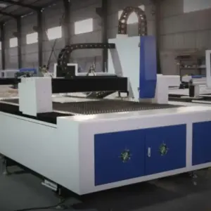
2.0 Technical Analysis of the 12kW Fiber Source Dynamics
The core of the system is a 12kW ytterbium-doped fiber laser source. At this power density, the energy-matter interaction undergoes a distinct shift compared to lower-wattage 4kW or 6kW systems.
2.1 Kerf Consistency and Melt Dynamics
With 12kW of power, the cutting speed on 20mm to 30mm structural carbon steel (S355JR or similar) is significantly increased, which paradoxically reduces the total heat input into the workpiece. By maintaining a high feed rate, the Heat Affected Zone (HAZ) is restricted to a depth of less than 0.2mm. This is vital for wind turbine internals, where structural integrity and resistance to vibration-induced fatigue are paramount.
2.2 Nitrogen vs. Oxygen Processing
While oxygen-assisted cutting is utilized for thicknesses exceeding 20mm to maintain low-pressure gas consumption, the 12kW source allows for “High-Pressure Air” or Nitrogen cutting on mid-range thicknesses (10mm-15mm). In the Charlotte facility, this has resulted in oxide-free edges, facilitating immediate paint adhesion or welding without the need for acid pickling or mechanical wire brushing.
3.0 ±45° Bevel Cutting Kinematics and Weld Preparation
The most significant advancement in this 12kW system is the integration of a high-torque, 5-axis robotic cutting head capable of ±45° tilting. In wind turbine tower construction, internal platforms and ladder supports require complex intersections between curved shell walls and linear beams.
3.1 Geometry of the Bevel
Traditional perpendicular cutting requires a subsequent manual beveling stage to create V, Y, or K-groove weld preparations. The CNC system’s ability to execute a ±45° bevel directly on the beam flange or web eliminates this secondary station. The Charlotte field tests demonstrated that the system maintains a ±0.5mm dimensional tolerance across a 12-meter beam length, even when executing varying bevel angles along a single contoured path.
3.2 Compensation for Beam Camber and Sweep
Structural steel is rarely perfectly straight. The CNC laser system utilizes a series of mechanical and optical sensors (laser line scanners) to map the actual profile of the beam in real-time. The 12kW cutting head adjusts its Z-axis and tilt angle dynamically to compensate for “camber” (vertical deviation) and “sweep” (horizontal deviation). This ensures the bevel angle remains consistent relative to the material surface, rather than the theoretical CAD plane.
4.0 Application Specifics: Wind Turbine Towers in the Charlotte Sector
Charlotte’s industrial ecosystem serves as a primary supplier for both onshore and offshore wind projects across the Atlantic seaboard. The components processed by this 12kW system are primarily internal reinforcement rings, mezzanine support beams, and cable management channels.
4.1 Fatigue Resistance in High-Vibration Environments
Wind towers are subject to harmonic oscillations and extreme wind loading. A laser-cut edge, particularly one cut with 12kW precision, exhibits fewer micro-fissures and striations than a plasma-cut edge. By utilizing the ±45° beveling technology, the Charlotte facility has achieved a “fusion-ready” edge profile that facilitates deeper weld penetration and a more uniform stress distribution across the joint.
4.2 Throughput Metrics
Prior to the implementation of the 12kW CNC laser, a standard H-beam required approximately 45 minutes for layout, manual cutting, and bevel grinding. The automated 12kW system completes the same sequence—including bolt-hole piercing and beveling—in under 6 minutes. This represents an 800% increase in throughput for the “Ready-to-Weld” (RTW) component stream.
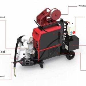
5.0 The Synergy of 12kW Power and Automatic Structural Processing
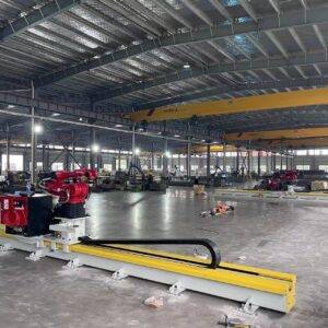
The integration of a high-power source with a 3D structural handling system (in-feed/out-feed conveyors and rotary chucks) creates a closed-loop manufacturing environment.
5.1 Material Handling and Chuck Synchronization
For beams and channels, the 12kW system employs a dual-chuck or triple-chuck architecture. The CNC must synchronize the rotation of the beam with the movement of the 5-axis head. The high power of the 12kW source means that the dwell time during piercing is negligible (less than 0.5 seconds for 20mm steel), which prevents “slug welding” or thermal blooming that can occur with lower-power sources.
5.2 Nesting and Scrap Reduction
Advanced nesting software, integrated with the CNC controller, allows for “common line cutting” even on beveled edges. In the Charlotte deployment, this has led to a 12% reduction in raw material waste. The software calculates the optimal orientation of the ±45° cuts to minimize the distance between parts on the H-beam, accounting for the kerf width of the 12kW beam.
6.0 Technical Challenges and Field Solutions
During the commissioning phase in Charlotte, two primary technical challenges were addressed: back-reflection and thermal lensing.
6.1 Back-Reflection Mitigation
When cutting highly reflective or thick-section structural steel at high power, back-reflection can damage the fiber delivery system. The 12kW head utilized in this deployment features an optical isolator and a real-time back-reflection monitoring system that adjusts the beam frequency or shuts down the pulse if a critical threshold is reached.
6.2 Thermal Lensing in 5-Axis Heads
High-power lasers generate significant heat within the cutting head optics. In a 5-axis environment where the head is constantly tilting, this heat can cause “focus shift” or “thermal lensing,” altering the focal point of the laser. The solution implemented was a dual-cooled collimation and focusing lens system, using a high-flow deionized water loop to maintain optical stability within ±10 microns of the focal plane during 100% duty cycle operations.
7.0 Conclusion: The New Standard for Structural Steel
The deployment of the 12kW CNC Beam and Channel Laser Cutter in Charlotte marks a transition from “fabrication” to “precision engineering” in the wind energy sector. The ability to combine high-wattage throughput with the geometric flexibility of ±45° beveling allows for the production of structural members that are dimensionally superior and metallurgically sound.
The removal of the “manual grinding bottleneck” ensures that the Charlotte facility can meet the aggressive delivery timelines required for regional wind farm expansions. Future iterations will likely focus on further integrating AI-driven defect detection within the CNC loop to ensure 100% weld-ready certification without manual inspection.
End of Report
Lead Engineer, Structural Laser Division
Field Operations – Charlotte, NC