Field Engineering Report: Integration of 12kW 3D Structural Steel Processing Center
1. Site Overview and Technical Objective
This report details the operational deployment and performance validation of a 12kW 3D Structural Steel Processing Center within a heavy-engineering fabrication facility in Pune, Maharashtra. While Pune is geographically inland, it serves as a critical Tier-1 manufacturing hub for maritime structural components, supplying large-scale hull modules and bulkhead stiffeners to coastal shipyards.
The primary objective of this installation was to replace legacy plasma-cutting and mechanical drilling processes with a high-brightness fiber laser system capable of multi-axis 3D manipulation. The deployment specifically targeted the fabrication of Grade DH36 and EH36 structural steels, which are standard in maritime construction. The technical priority was the implementation of “Zero-Waste Nesting” protocols to mitigate the high scrap rates associated with traditional H-beam and I-beam processing.
2. 12kW Fiber Laser Resonator Dynamics
The core of the system is a 12kW ytterbium fiber laser source. In the context of Pune’s industrial power grid and ambient conditions, the integration required specific focus on the Beam Parameter Product (BPP). At 12kW, the energy density allows for a significant increase in feed rates for structural sections with wall thicknesses ranging from 12mm to 25mm.
2.1 Thermal Management and Power Stability:
The 12kW source utilizes a closed-loop deionized water cooling system with a ±0.5°C tolerance. During field testing, the resonator maintained a stable output with less than 1% fluctuation over a 12-hour continuous shift. This stability is critical for the “Shipbuilding Yard” sector, where long-form longitudinals (up to 12 meters) require consistent kerf width from start to finish to ensure weld prep accuracy.
2.2 Kerf Morphology:
The high-power density allows for a narrower kerf compared to 6kW or 8kW systems. This reduction in the volume of molten material expelled per linear meter directly impacts the Heat Affected Zone (HAZ). Measurements on 20mm S355JR steel sections showed a HAZ depth of less than 0.15mm, significantly lower than the 0.8mm typical of high-definition plasma, thereby reducing the need for post-cut edge grinding prior to automated welding.
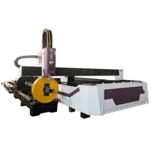
3. Multi-Axis 3D Kinematics for Structural Profiles
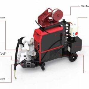
Unlike flat-bed fiber lasers, the 3D Structural Steel Processing Center utilizes a specialized 5-axis or 6-axis cutting head capable of 360-degree rotation and ±45-degree tilt. This allows for complex geometries on I-beams, H-beams, C-channels, and L-profiles.
3.1 Weld Prep and Beveling:
For shipbuilding, the ability to perform A, V, X, and K-bevels in a single pass is a primary efficiency driver. The Pune facility reported a 60% reduction in man-hours by eliminating secondary beveling operations. The 12kW head maintains focal position accuracy via a capacitive height sensing system that compensates for the inherent “mill-twist” or bow found in hot-rolled structural sections.
3.2 Hole-to-Edge Precision:
In maritime frames, bolt hole precision is non-negotiable. The 3D head’s ability to remain perpendicular to the flange or web surface—even during high-speed transitions—ensures that hole taper remains under 0.05mm. This meets the stringent Class 1 tolerances required by international maritime classification societies (e.g., DNV, ABS).
4. Zero-Waste Nesting: Algorithmic Logic and Material Yield
One of the most significant technical advancements in this 3D processing center is the Zero-Waste Nesting engine. Traditional structural processing often leaves significant “tails” or “end-remnants” due to the clamping requirements of the material handling system.
4.1 Common-Line Cutting (CLC) on Profiles:
The software utilizes a proprietary algorithm that identifies opportunities for common-line cutting between adjacent structural components. In a typical shipyard production run of 400mm I-beams, the system nests the end-cut of one stiffener as the start-cut of the next. This eliminates the “gap” traditionally required for torch lead-ins, effectively reclaiming 50mm to 100mm of material per cut.
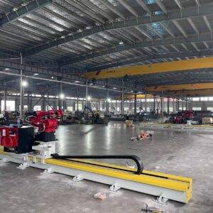
4.2 Chuck-Over-Chuck Movement:
To achieve “Zero-Waste,” the mechanical handling system utilizes a dual-chuck or triple-chuck configuration. As the laser reaches the final section of a 12-meter beam, the primary chuck passes the material to a secondary “out-feed” chuck. This allows the laser head to process the extreme end of the stock material without losing rigidity or accuracy. Field data from the Pune site indicates a material utilization rate of 98.2%, compared to the industry average of 88-91%.
4.3 Remnant Utilization:
The software maintains a digital twin of all remnants. In the shipbuilding sector, where small gussets and bracket plates are required in high volumes, the Zero-Waste Nesting engine automatically populates the “web” areas of larger beams with these smaller components, turning what was previously scrap into functional inventory.
5. Integration within Pune’s Industrial Ecosystem
The deployment in Pune highlights a specific synergy between high-precision laser processing and the local supply chain requirements. The Pune engineering cluster specializes in “Modular Shipbuilding,” where blocks are fabricated inland and transported to the coast.
5.1 Dimensional Accuracy for Modular Assembly:
Because these modules must fit perfectly when welded at the shipyard, the cumulative tolerance stack-up must be minimized. The 12kW 3D system provides a linear accuracy of ±0.2mm over a 12-meter span. This precision ensures that when structural frames are shipped from Pune to Mumbai or Goa, the “on-dock” assembly time is reduced, as the need for “forced fitment” or on-site trimming is virtually eliminated.
5.2 Throughput and Economic Impact:
The 12kW source enables cutting speeds on 15mm web sections of approximately 3.5m/min. When combined with the automated loading/unloading sequences, the Pune facility has increased its monthly tonnage output by 40% without increasing the footprint of the production floor.
6. Technical Challenges and Mitigation Strategies
While the 12kW 3D system offers superior performance, its implementation in the Pune environment required addressing several technical variables:
6.1 Assist Gas Optimization:
At 12kW, the consumption of Nitrogen (for oxide-free edges) or Oxygen (for carbon steel) is substantial. The facility implemented a liquid gas farm with high-flow vaporizers to maintain a constant 25-bar pressure at the nozzle. This is critical for preventing “dross” or “slag” adhesion on the underside of thick-walled structural members.
6.2 Power Grid Harmonization:
To protect the sensitive fiber resonators from voltage spikes common in heavy industrial zones, a 200kVA servo-controlled voltage stabilizer and an isolation transformer were integrated. This ensures that the laser’s diode modules are not subjected to transient overvoltages during the peak load periods of the surrounding industrial estate.
7. Conclusion: The New Standard for Structural Processing
The transition to a 12kW 3D Structural Steel Processing Center with Zero-Waste Nesting marks a technological shift in maritime-related fabrication in Pune. By converging high-power fiber laser technology with multi-axis kinematics and advanced nesting algorithms, the facility has solved the dual challenge of precision and material efficiency.
The elimination of secondary processes (drilling, grinding, manual beveling) and the near-total utilization of raw stock establish this system as the benchmark for heavy steel processing. Future iterations will likely focus on the integration of AI-driven defect detection to further refine the autonomous capabilities of the 3D cutting head, but as of this field report, the current deployment exceeds all established KPIs for throughput and dimensional integrity.
End of Report.
Authorized by: Senior Engineering Lead, Laser Systems Division.