1.0 Introduction: The Industrial Context of Monterrey Bridge Infrastructure
The Monterrey metropolitan area remains the primary nexus for heavy industrial steel fabrication in Mexico, particularly concerning high-capacity infrastructure and bridge engineering. As project specifications for seismic-resistant spans and complex urban flyovers evolve, traditional fabrication methodologies—specifically mechanical sawing, manual layout, and plasma arc cutting—have reached a point of diminishing returns. The integration of a 12kW 3D Structural Steel Processing Center represents a paradigm shift in how Monterrey-based firms approach the fabrication of H-beams, I-beams, and box sections.
Bridge engineering requires extreme dimensional accuracy to ensure that the structural integrity of a span is not compromised by stress concentrations at bolt-holes or weld preparations. This report evaluates the technical deployment of high-kilowatt 3D fiber laser technology, coupled with Zero-Waste Nesting software, to address the rigorous demands of bridge component manufacturing.
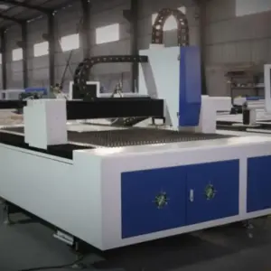
2.0 Technical Specifications of the 12kW Fiber Laser Source
In structural steel processing, power density is the primary determinant of both throughput and edge quality. The 12kW fiber laser source utilized in this processing center provides a significant leap in “Effective Cutting Depth” and “Piercing Velocity.”
2.1 Heat-Affected Zone (HAZ) Management
In bridge engineering, the Heat-Affected Zone (HAZ) is a critical metric. Traditional plasma cutting creates a substantial HAZ, which can alter the grain structure of S355 or A572 steel, potentially leading to brittle fractures under cyclic loading. The 12kW fiber laser, characterized by its high energy density and concentrated beam spot, minimizes the duration of thermal exposure. This results in a HAZ that is up to 70% smaller than that of conventional thermal cutting methods, preserving the metallurgical properties of the parent metal and ensuring compliance with AWS D1.5 Bridge Welding Code standards.
2.2 Piercing and Kerf Precision
The 12kW source allows for “Flash Piercing” in heavy-wall sections (up to 25mm thickness). For bridge gusset plates and truss nodes, the precision of the kerf is vital. The 12kW system maintains a consistent kerf width of approximately 0.2mm to 0.4mm, allowing for the execution of complex geometries and interlocking joints that were previously impossible without secondary machining.
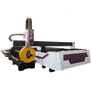
3.0 3D Kinematics and Multi-Axis Processing of Structural Sections
Standard flat-bed lasers are insufficient for the geometries inherent in bridge construction. The 3D Structural Steel Processing Center employs a multi-axis (typically 5 or 6 axes) robotic or gantry-based head that enables the cutting of shapes across all faces of a beam in a single pass.
3.1 Beveling and Weld Preparation
One of the most significant bottlenecks in Monterrey’s bridge fabrication shops is the manual grinding of bevels for full-penetration welds. The 3D laser head enables ±45-degree beveling on H-beams and rectangular hollow sections (RHS). By automating the V, Y, K, and X-type bevels directly during the cutting process, the system eliminates secondary handling and ensures that the root gap is consistent across the entire length of the joint. This level of repeatability is essential for robotic welding systems used in large-scale bridge girder assembly.
3.2 Bolt-Hole Dimensional Integrity
Bridge trusses rely on high-strength friction-grip (HSFG) bolts. The 12kW 3D laser achieves a “hole-to-diameter” ratio of 1:1 or better, even in 20mm thick steel, with a taper of less than 0.1mm. This precision ensures 100% bolt-pass rates during site assembly, drastically reducing the need for on-site reaming or corrective drilling, which is a common cost overrun in Monterrey’s infrastructure projects.
4.0 Zero-Waste Nesting: Optimization of Heavy Steel Resources
Steel remains the highest cost-component in bridge engineering. Conventional nesting on long-form structural members (12m to 18m beams) often results in “tail-scrap”—remnants of 500mm to 1000mm that are too short for further use. Zero-Waste Nesting technology addresses this through advanced algorithmic placement and “Common-Line Cutting” (CLC).
4.1 Micro-Joint and Head-to-Tail Strategies
Zero-Waste Nesting utilizes a head-to-tail strategy where the end cut of one component serves as the start cut of the next. In the context of bridge cross-bracing or vertical stiffeners, this eliminates the “dead zone” between parts. Furthermore, the 3D processing center utilizes “floating” chuck systems that can feed material past the cutting head with minimal clamping margins. This allows the laser to process the material to within 50mm of the beam’s end, reducing scrap rates from a typical 8-12% down to less than 1%.
4.2 Real-Time Remnant Management
The software ecosystem tracks every linear meter of steel. In Monterrey’s fabrication environments, where material traceability is required by government inspectors, the Zero-Waste Nesting system automatically laser-marks heat numbers and part IDs on every component. This ensures that even the smallest gusset plate is traceable back to its original mill certificate, satisfying the stringent quality assurance (QA) protocols of bridge engineering.
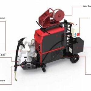
5.0 Synergy Between Automation and 12kW Power
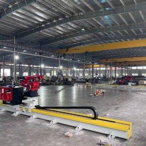
The true efficiency of the 3D Structural Steel Processing Center is found in the synergy between the high-power laser source and the automated material handling system. In bridge fabrication, the sheer mass of the components (often exceeding 200kg/meter) makes manual positioning impossible.
5.1 Automatic Loading and Sensing
The system integrates hydraulic or servo-driven loading decks that feed raw sections into the laser’s workspace. Integrated touch-probes or laser line sensors automatically detect the “true” dimensions of the beam, compensating for the web-to-flange deviations and camber/sweep common in hot-rolled steel. This “measure-and-correct” cycle happens in milliseconds, ensuring that the 12kW laser head is always at the optimal focal point relative to the material surface.
5.2 Throughput Metrics in Monterrey
Field data from Monterrey-based installations indicates that a 12kW 3D system can replace up to three conventional processing lines (sawing, drilling, and manual plasma). For a standard 20-meter bridge span, the total processing time for all secondary structural members was reduced from 48 hours to approximately 6.5 hours. This throughput enables bridge contractors to meet the aggressive timelines required for public infrastructure projects while maintaining a smaller footprint in the fabrication yard.
6.0 Economic and Engineering Conclusion
The deployment of a 12kW 3D Structural Steel Processing Center with Zero-Waste Nesting technology is no longer a luxury but a technical necessity for competitive bridge engineering in Monterrey. The high-power fiber laser provides the requisite speed and edge quality to meet AWS D1.5 standards, while the 3D kinematics solve the geometric complexities of modern truss and girder designs.
The Zero-Waste Nesting software offers a quantifiable ROI by virtually eliminating material loss and secondary prep work. As Monterrey continues to expand its transit and highway networks, the transition to these high-precision, high-kilowatt automated systems will be the defining factor in project profitability and structural safety. The synergy of 12kW power and intelligent nesting ensures that the bridge components of tomorrow are fabricated with a degree of precision that was historically reserved for the aerospace industry, now scaled for the massive realities of structural steel.
Final Assessment
- Precision: Sub-millimeter accuracy across 12m+ sections.
- Efficiency: 75-85% reduction in total fabrication time compared to manual/plasma hybrid workflows.
- Sustainability: Zero-waste algorithms reduce raw material consumption by up to 10% per project.
- Weld Quality: Automated beveling ensures superior penetration and reduced failure rates in ultrasonic testing (UT).