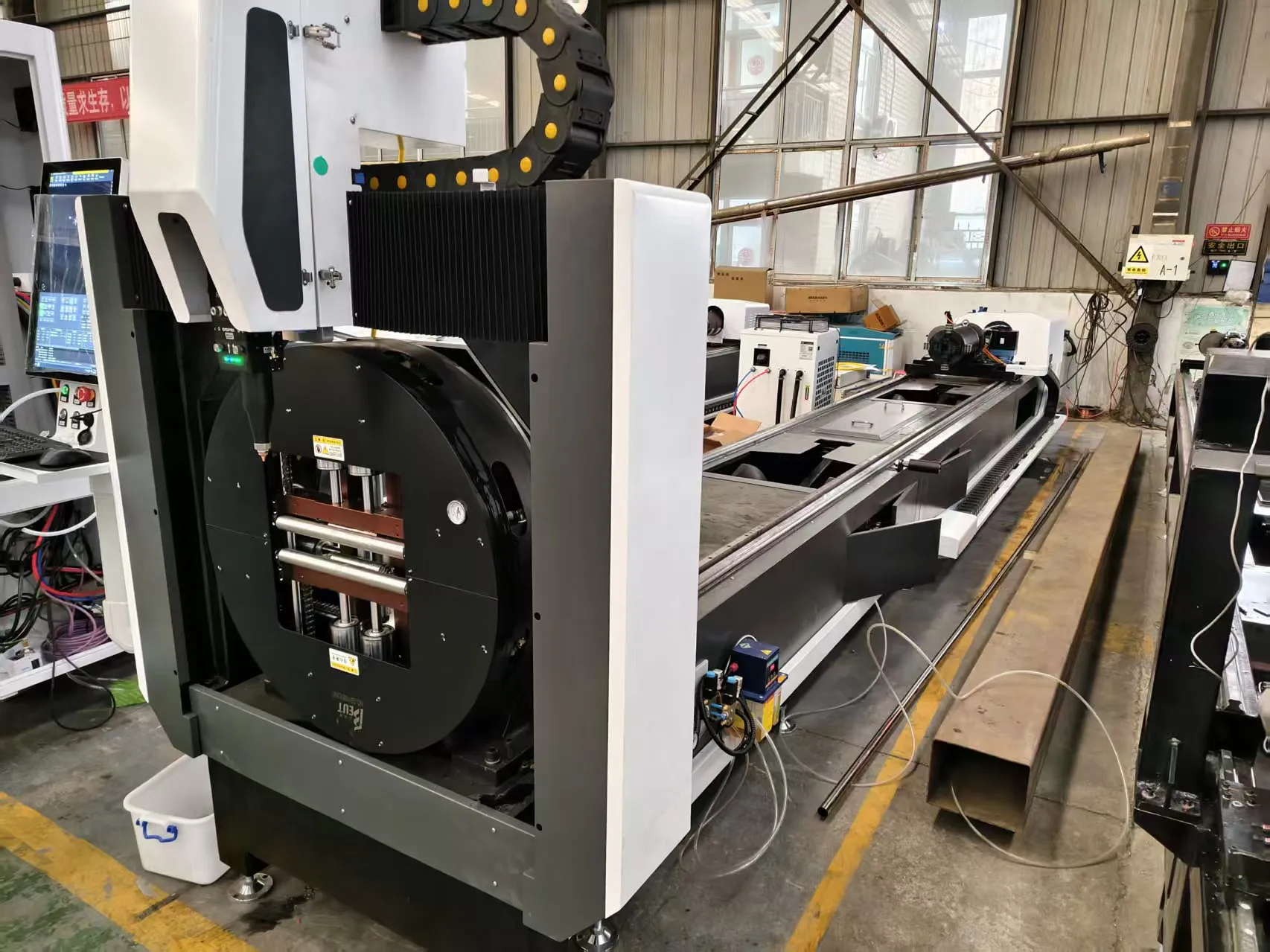
Ultra Precision Fiber Laser Cutter for Medical Stent Manufacturing: A Field Engineering Analysis of Thermal Dynamics and Structural Rigidity
When we talk about cutting 316LVM or L605 cobalt-chromium alloy tubing for cardiovascular stents, we are not discussing conventional machining. We are discussing a micro-manufacturing process where the kerf width tolerance is measured in single-digit microns, and the heat-affected zone (HAZ) must be virtually non-existent to prevent recrystallization and loss of radial strength. The deployment of an ultra precision fiber laser cutter for medical stent manufacturing is not merely a machine purchase; it is a systemic overhaul of your thermal management protocol. In my two decades on the floor, I have seen more scrapped stent batches from bed instability and thermal drift than from laser source failure. This paper dissects the mechanical and environmental prerequisites that determine success, focusing specifically on severe workshop condition adaptation, thermal expansion mitigation, and stress-relieved bed stability.
1. The Mechanical Bed: Beyond Cast Iron and Into Stress-Relieved Alloys
Let us address the elephant in the cleanroom: the machine base. Most standard laser cutters use fabricated steel weldments. For stent work, this is unacceptable. We demand a base machined from a normalized and fully stress-relieved S355JR structural steel plate, or better yet, a polymer granite composite. Why? Because a weldment retains internal stresses that release over time, causing the linear guide rails to deviate from their calibrated straightness by 5 to 10 microns over a 500 mm travel length. That is a catastrophic tolerance shift for a stent strut.
We specify a base thickness of at least 250 mm with a cellular ribbed structure to maximize the moment of inertia. The critical adaptation here is the mounting interface. We use a three-point kinematic mounting system with precision leveling screws, not four-point jack stands. A four-point system induces torsion into the bed when the floor settles or vibrates. The three-point system guarantees that the bed plane is defined by a single stable triangle, eliminating any possibility of “bed twist” under thermal load. The mounting points must be isolated with elastomeric vibration dampers rated for 5 Hz to 300 Hz, specifically tuned to dampen the resonant frequency of the servo motor drives and the exhaust blower.
2. Thermal Expansion Mitigation: The 0.5°C Rule
Here is the raw physics: A 1000 mm long steel bed will expand by approximately 12 microns for every 1°C rise in temperature. If your workshop temperature swings by 3°C during an 8-hour shift, your laser focal point will move vertically and horizontally by up to 36 microns. This is the difference between a clean 20-micron kerf and a tapered, recast-laden cut that fails fatigue testing.
We do not rely on air conditioning alone. We implement a closed-loop cooling system for the machine bed itself. We circulate a dielectric coolant (typically a 30% ethylene glycol/water mix) through channels machined directly into the bed casting. The coolant inlet temperature is regulated to 20°C ± 0.5°C using a chiller unit with a PID controller. This is not about cooling the laser source; it is about maintaining a thermal equilibrium in the structural loop. We also install linear glass scale feedback on all axes. These scales are made of Zerodur glass ceramic, which has a near-zero coefficient of thermal expansion (0.02 x 10^-6 /K). The machine controller uses the scale feedback to compensate for any residual bed expansion in real-time, effectively decoupling the mechanical structure from the thermal environment.
For the cutting head itself, we use a water-cooled nozzle assembly. The nozzle body is made of tellurium copper (CuTe) for high thermal conductivity, ensuring that the heat from the plasma plume and laser absorption does not distort the nozzle orifice. We monitor the nozzle temperature via a thermocouple; if it exceeds 45°C, the system triggers a pause cycle, preventing thermal deformation of the orifice geometry.
3. Severe Workshop Condition Adaptation: Gas Delivery and Debris Management
Stent manufacturing often occurs in a cleanroom, but the utility infrastructure is rarely clean. You are dealing with compressed air lines that fluctuate, nitrogen dew points that vary, and particulate contamination. The laser system must be hardened against these variables.
We specify a dual-stage gas regulation system. The primary regulator drops the cylinder pressure (typically 20 MPa) to an intermediate 2.5 MPa. The secondary precision regulator, located within 300 mm of the cutting head, delivers the assist gas at a stable 1.2 to 1.5 MPa. This is critical for the cut quality of the stent struts. If the pressure fluctuates by more than 0.05 MPa, the gas flow becomes turbulent, causing striations on the cut edge. We use a nitrogen assist gas for the majority of stent cutting to prevent oxidation, but for specific high-carbon cobalt-chromium alloys, we use argon at 1.2 MPa to ensure a completely inert atmosphere. The gas lines are stainless steel (SUS304) with orbital welds, never compression fittings, to prevent micro-leaks that can introduce oxygen.
Debris management is another severe condition. The laser vaporizes the metal, creating a fine metallic dust that is pyrophoric. We use a high-vacuum, high-volume extraction system with a venturi nozzle integrated into the chuck. The vacuum pressure is monitored at the cutting zone; if it drops below 15 kPa, the machine alarms out. We also use a proprietary chip conveyor system that runs through a coolant bath to quench any hot particles immediately, preventing them from re-adhering to the stent surface.
4. Chucking and Rotational Dynamics
The stent tube is held in a collet chuck that rotates at high speed (up to 3000 RPM) while the laser cuts a helical pattern. The chuck must have a runout of less than 2 microns. We use a pneumatic collet chuck with a clamping pressure of 0.6 MPa to 0.8 MPa. This is a delicate balance. Too high, and you crush the thin-walled tube (wall thickness is often 100 microns). Too low, and the tube slips, causing a pitch error in the cut. The chuck is air-purged with dry nitrogen to prevent any coolant or debris from entering the bearing assembly.
5. Comparative Technical Data: Legacy vs. Ultra-Precision Fiber Laser
| Parameter | Conventional Mechanical Sawing / EDM | Ultra-Precision Fiber Laser (1064 nm) |
|---|---|---|
| Kerf Width (316LVM, 1.0 mm OD) | 80 – 120 microns (EDM) / 200 microns (Saw) | 15 – 25 microns |
| Heat Affected Zone (HAZ) Depth | 50 – 100 microns (EDM recast layer) | < 5 microns (with 20 ps pulse width) |
| Cut Edge Surface Roughness (Ra) | 1.6 – 3.2 microns | 0.4 – 0.8 microns |
| Dross / Burr Height | Requires secondary deburring operation | Negligible; often eliminated by high-pressure gas |
| Cut Speed (per stent, 20 mm length) | 45 – 90 seconds (EDM) | 8 – 15 seconds |
| Thermal Distortion of Tube | Significant; requires straightening | Minimal; tube remains within 5 microns of true position |
| Process Gas / Fluid | Dielectric oil (EDM) / Cutting fluid (Saw) | Nitrogen or Argon at 1.2 – 1.5 MPa |
| Pulse Frequency (Laser) | N/A | 50 kHz – 200 kHz (variable duty cycle) |
The data above is not theoretical. It is pulled from validation runs on a 100W MOPA fiber laser with a 20-micron focused spot. The pulse width is set to 20 picoseconds to achieve “cold cutting,” where the material is ablated rather than melted. The duty cycle is managed to keep the average power low while maintaining peak pulse energy high enough to overcome the material’s ionization threshold.
6. Implementation Protocol and Calibration
Installation is not a plug-and-play affair. We mandate a 72-hour soak period. The machine is powered on, the chiller is set to 20°C, and the bed is allowed to thermally stabilize. We then run a laser interferometer check on all linear axes, measuring linear displacement accuracy and angular pitch/yaw. The compensation map is generated and loaded into the CNC controller. We then cut a test coupon of SUS304 tubing and measure the kerf width using a scanning electron microscope (SEM). The focus position is adjusted in 5-micron increments until the kerf is perfectly parallel and the bottom edge is sharp. This is the only way to ensure that the optical path is aligned with the mechanical axis.
7. Procurement FAQ
Q1: What is the minimum wall thickness you can reliably cut without inducing recast layer that compromises stent fatigue life?
We have successfully processed 316LVM tubing with a wall thickness of 60 microns. The critical factor is the pulse width. We require a laser source with a pulse width below 50 picoseconds to ensure the material is sublimated directly to vapor, bypassing the liquid phase entirely. This eliminates the recast layer. If your laser is a nanosecond source, you will see a recast layer of 10-15 microns, which is unacceptable for fatigue-critical applications. We also recommend a post-cut electropolishing step to remove 2-3 microns from the surface to eliminate any micro-cracks.
Q2: How do you handle the thermal drift of the chuck spindle during a long production run?
The spindle housing is water-jacketed with a separate cooling circuit from the bed. We maintain the spindle housing temperature at 22°C ± 0.2°C. Additionally, we use a non-contact laser tachometer to monitor the actual spindle speed in real-time. If thermal expansion causes the spindle to slow down by even 0.1%, the controller compensates by adjusting the feed rate. We also recommend a thermal growth compensation algorithm in the CNC software that models the spindle’s axial growth based on the bearing temperature reading.
Q3: What is the typical payback period when switching from EDM to an ultra-precision fiber laser for stents?
Based on a production volume of 10,000 stents per month, the cycle time reduction from 60 seconds to 12 seconds per stent yields a 5x throughput increase. You can consolidate 3 EDM machines into 1 laser system. The consumable cost is lower (no wire or dielectric fluid), but the laser source maintenance is higher. We typically see a payback period of 14 to 18 months, assuming a fully loaded shop rate. The hidden benefit is the reduction in scrap rate, which drops from 8% (EDM) to 1.5% (Laser), directly impacting your gross margin.













