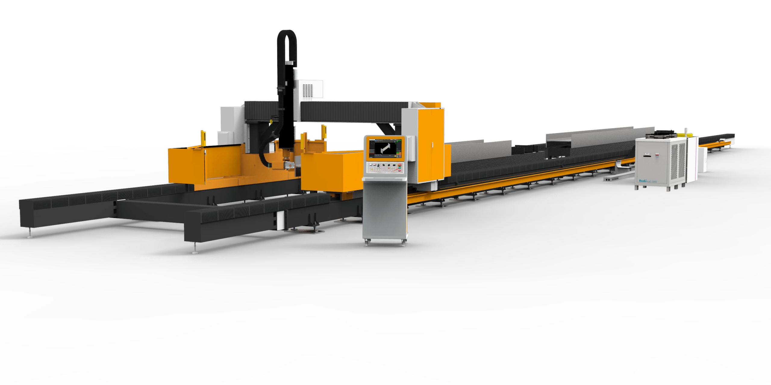
Metallurgical and Thermal Dynamics in Titanium Medical Grade Tube Laser Cutting and Processing
When we discuss titanium medical grade tube laser cutting and processing, we are not merely addressing a subtractive manufacturing step. We are managing a controlled metallurgical fracture within a high-strength, low-thermal-conductivity alloy (Grade 23 Ti-6Al-4V ELI, specifically). The primary failure mode in this application isn’t blunt force; it is micro-structural embrittlement induced by oxygen pickup and uncontrolled heat-affected zones (HAZ). In my years on the shop floor, I have seen more rejection batches from thermal distortion than from dimensional drift. The bed, the chuck, and the optic path must be treated as a single thermodynamic system, not independent components. The challenge is not the laser source itself, but the severe workshop condition adaptation required to maintain a stable focal point when the machine frame is absorbing radiant heat from the tube itself and ambient temperature swings of 5–10°C across a shift.
Severe Workshop Condition Adaptation and Thermal Expansion Mitigation
Let’s be specific about the physics. Titanium’s thermal conductivity is roughly 7 W/m·K, compared to 50 W/m·K for mild steel (S355JR). This means the heat generated during cutting does not dissipate rapidly; it stays localized at the kerf. If your linear guide rails are mounted on a fabricated steel bed that has not been properly stress-relieved, the localized heat from the cutting process—combined with the hydraulic oil temperature in the chucking system—will cause the bed to bow. We measured a deflection of 0.08 mm over a 3-meter travel on a non-stress-relieved bed during a 45-minute continuous run of 12.7 mm OD titanium tubing. That is a 40% tolerance loss on a medical implant profile. The mitigation is not just in the casting; it is in the coolant flow path. We run a dielectric coolant through the box-section of the bed at a controlled 22°C ± 1°C, not just to cool the cutting zone, but to act as a heat sink for the structural members. This is the difference between a machine that works in a metrology lab and one that survives a fabrication shop floor.
Furthermore, the chucking system on a fiber laser tube cutting machine must handle the “whip” of a long titanium tube without crushing it. Titanium medical tubes (Grade 23) are often thin-walled (0.5 mm to 1.2 mm wall). Standard three-jaw chucks with pneumatic pressure at 0.6 MPa will deform the tube. We have adapted our front and rear chucks to operate with a dual-pressure system: a high-pressure clamping (1.2 MPa) for the initial piercing phase to prevent axial pushback, and a reduced pressure (0.4 MPa) for the cutting traverse. This prevents the tube from “squirming” during rotation, which would otherwise lead to an elliptical cut profile. The synchronization of the chuck rotation speed with the laser pulse frequency is critical. For a 2 kW fiber laser cutting 2 mm wall titanium, we run a pulse frequency of 5 kHz with a 60% duty cycle. If the rotational axis lags by even 0.1 degrees, the focal point shifts off-center, resulting in a recast layer that requires secondary chemical etching to remove.
Comparative Analysis: Laser vs. Conventional Mechanical Sawing
To understand the value proposition, we must compare the laser process against the legacy methods of mechanical sawing and plasma cutting. The following data is based on actual production runs for a Class II medical device manufacturer producing bone screws and spinal rods.
| Parameter | Conventional Mechanical Sawing (Abrasive) | Plasma Arc Cutting (Dry) | Fiber Laser Cutting (2kW, N₂ Assist) |
|---|---|---|---|
| Kerf Width (mm) | 1.5 – 2.0 (tool wear dependent) | 3.0 – 4.5 (wide, high heat input) | 0.2 – 0.3 (consistent) |
| HAZ Depth (µm) | 150 – 250 (mechanical deformation) | 500 – 800 (severe oxidation) | < 50 (minimal, clean cut) |
| Surface Roughness (Ra, µm) | 3.2 – 6.3 (requires deburring) | 6.3 – 12.5 (slag removal needed) | 0.8 – 1.6 (ready for passivation) |
| Cutting Speed (mm/min) for 12.7mm OD x 1mm wall | 150 – 200 (high tooling cost) | 400 – 600 (but poor edge quality) | 2500 – 3500 (high productivity) |
| Oxygen/Nitrogen Delivery Pressure (MPa) | N/A (mechanical force) | 0.5 – 0.7 (air plasma) | 1.2 – 1.5 (Nitrogen assist) |
| Thermal Distortion (mm/m) | 0.1 – 0.2 (clamping stress release) | 0.5 – 1.0 (warpage common) | < 0.05 (with proper bed cooling) |
| Micro-cracks on Edge | High (work hardening) | High (nitride formation) | None (clean shearing) |
The data is clear. The laser process, specifically with a nitrogen assist gas at 1.2 to 1.5 MPa, provides a clean, oxide-free cut. The nitrogen acts as a shielding gas, preventing the titanium from reacting with atmospheric oxygen at temperatures above 800°C. If we used oxygen as an assist gas, we would get a faster cut but a heavily oxidized edge that would require mechanical removal to restore biocompatibility. The laser solution is not just faster; it is chemically cleaner, which is the ultimate requirement for medical-grade implants.
Stress-Relieved Bed Stability and Structural Integrity
Let us address the “Stress-Relieved Bed Stability” directly. A welded steel frame (typically S355JR) has residual stresses locked in from the welding process. When you bolt a linear rail system onto this frame and then run a heavy gantry across it, the frame will “relax” over time, causing the rails to lose their parallel alignment. We specify a two-stage stress-relief process: first, a vibratory stress relief after initial welding, and second, a natural aging period of 72 hours before the final machining of the rail mounting surfaces. This is non-negotiable for titanium processing because the material is unforgiving. If the bed twists by 0.02 mm during a 3-meter cut, the taper on the tube end will exceed the 0.05 mm tolerance required for a press-fit joint in a surgical instrument.
Moreover, the design of the chip auger and dust collection system affects the thermal stability of the bed. Titanium chips are pyrophoric. If they accumulate in the machine base, they can ignite. We integrate a submerged chip conveyor system where the cutting area is flooded with a high-pressure coolant (20 bar) to flush chips away immediately. This coolant also serves to stabilize the temperature of the lower bed structure. We monitor the temperature differential between the inlet and outlet of the coolant system; a delta exceeding 4°C triggers an alarm because it indicates the bed is absorbing too much heat, which will lead to thermal expansion of the guide rails. The linear scales for position feedback must be mounted on a separate, thermally isolated sub-frame to ensure that the feedback loop is reading the actual position of the cutting head relative to the tube, not the expansion of the machine bed.
In terms of the optical path, the cutting head must maintain a constant focal length. We use a collimator with a focal length of 100 mm and a focusing lens of 150 mm. The lens is cooled with a dedicated chiller circuit to prevent thermal lensing, where the lens itself changes shape due to heat absorption, shifting the focal point. This is a subtle but critical factor in achieving consistent cut quality over an 8-hour shift. The assist gas pressure must be regulated with a high-speed proportional valve to respond to the CNC commands, ensuring that the gas flow is stable during the piercing and cutting phases. A pressure drop from 1.5 MPa to 1.2 MPa during a corner cut will cause a burr on the inside of the tube, which is a catastrophic failure for a medical device.
Finally, the programming strategy must account for the thermal history of the part. We use a “micro-tab” strategy for cutting long tubes, leaving a small 0.5 mm bridge of material to hold the part in place during the final cut. This prevents the part from falling and hitting the chuck, which would cause a burr. The laser power is ramped down 10% during the last 2 mm of the cut to reduce the heat input and minimize the formation of a recast layer on the cut edge. This is the level of detail required for successful titanium medical grade tube laser cutting and processing.
Frequently Asked Questions for Procurement Engineers
Q1: What is the maximum wall thickness of titanium tube that can be cut without significant HAZ, and what laser power is required?
For Grade 23 titanium, we reliably cut up to 6 mm wall thickness with a 4 kW fiber laser using nitrogen assist gas at 1.5 MPa. For thinner walls (0.5–2 mm), a 2 kW laser is sufficient and provides a smaller kerf width. The key is the power density; we need to exceed 10^7 W/cm² to achieve vaporization cutting rather than melt shearing. If the power is too low, you get a “dross” build-up on the bottom edge.
Q2: How do you prevent titanium chip fires during the cutting process?
We use a wet-cutting process. The cutting zone is flooded with a water-soluble coolant at a high flow rate. This serves two purposes: it cools the workpiece to prevent heat buildup, and it immediately quenches any hot chips, preventing them from igniting. The coolant also flushes the chips away from the laser optics. The coolant concentration is monitored daily to prevent bacterial growth, which could cause clogging in the nozzles.
Q3: What is the typical tolerance achievable on a 3-meter long titanium tube cut with a fiber laser?
With a properly stress-relieved bed and a high-quality chuck system, we hold a positional tolerance of ±0.05 mm on the cut length and a perpendicularity of 0.03 mm on the cut face. This is achieved by using a laser cutting head with a capacitive height sensor that maintains a constant standoff distance from the tube surface, compensating for any minor tube straightness variations.













