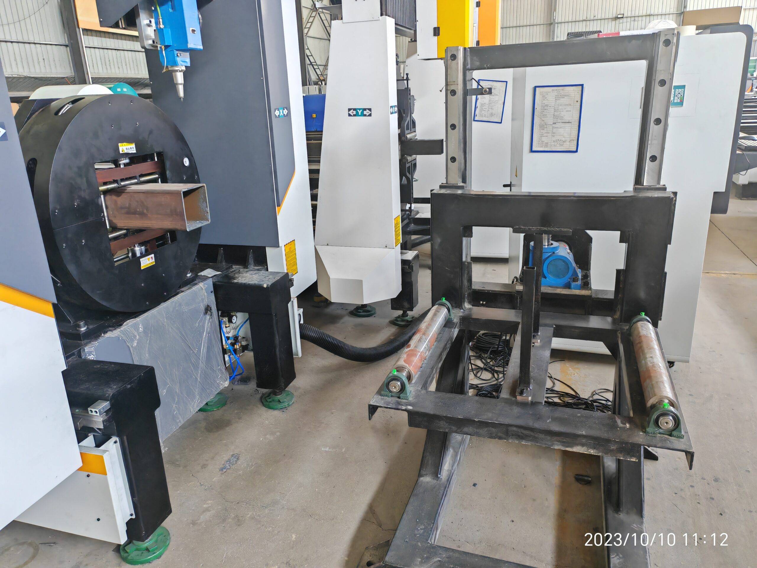
Operational Realities of High-Volume Solar Torque Tube and Pile Fabrication
Utility scale solar tracker manufacturing lines live or die by throughput consistency. When you are cutting 60,000 to 120,000 meters of tube per month across a single shift, the margin between profit and scrap is measured in millimeters of kerf and seconds of cycle time. The integration of smart nesting software for utility scale solar tube fabrication is not a luxury upgrade; it is the central nervous system that dictates whether your fiber laser cells operate at 85% OEE or collapse under the weight of unplanned downtime and material waste.
This analysis focuses on the post-installation phase: after-sales troubleshooting, consumables lifecycle management, and preventive maintenance. The goal is to move beyond the sales brochure and into the actual physics of cutting S355JR, SUS304, and Al6061 tubes at high duty cycles.
Nesting Logic and Its Direct Impact on Consumable Degradation
Smart nesting algorithms are typically marketed for yield optimization—squeezing more parts per meter. However, from a maintenance engineering perspective, nesting logic dictates the thermal load on the nozzle, the contamination rate of the protective lens, and the wear pattern on the chuck jaws.
Consider a standard 6-meter S355JR tube with a 3.0 mm wall thickness. A naive nesting pattern that places a pierce point directly over a previous cut edge or a weld seam forces the laser to pierce through inconsistent material density. This causes a phenomenon known as “pierce spatter blowback.” The molten metal ejected during the 0.8-second pierce cycle adheres to the nozzle tip. Over 500 pierces, this accumulation alters the standoff distance from the ideal 0.8 mm to an erratic 1.2–1.5 mm. The result is a defocused beam, a jagged cut edge, and a 40% reduction in nozzle life.
Smart nesting software mitigates this by applying “pierce point avoidance” and “common line cutting” strategies. By sharing the cut line between two adjacent parts, the software reduces the total pierce count by up to 30%. In a high-volume solar tube shop, this directly translates to:
- Nozzle life extension from 1,200 pierces to 1,800 pierces per tip (for 1.5 mm single-layer chrome-plated copper nozzles).
- Reduction in lens contamination events. Every 1,000 pierces avoided prevents approximately 0.3 grams of metallic vapor from depositing on the protective window.
- Stabilized thermal load on the chuck jaws. Uneven nesting creates hot spots on the tube surface, causing differential expansion that leads to slippage under 0.6 MPa pneumatic clamping pressure.
After-Sales Troubleshooting: The Physics of Cut Quality Drift
When a fiber laser cell begins producing dross on the bottom edge of a SUS304 tube, the operator’s first instinct is to adjust focus or speed. This is a mistake. The root cause is often a consumable lifecycle issue masked by software compensation.
For SUS304 with a 2.0 mm wall, the ideal cutting parameters using Nitrogen (N2) at 1.4 MPa are typically 3,500 W power, 12 m/min feed rate, and a frequency of 5,000 Hz. If the software detects a drop in cut quality and automatically slows the feed rate to 10 m/min to compensate, it is treating the symptom, not the disease. The disease is usually one of three things:
- Ceramic ring degradation: The ceramic insulator around the nozzle erodes after 300–400 hours of operation. A cracked ceramic causes capacitance feedback drift, leading to erratic height sensing. The software cannot correct for a hardware sensor that is lying.
- Protective lens thermal lensing: At 3,500 W continuous duty, the fused silica lens absorbs trace amounts of laser energy. After 800 hours, the focal shift can be 0.5 mm. The nesting software’s kerf compensation table becomes invalid.
- Chuck jaw wear: For Al6061 tubes, the serrated jaws wear down at a rate of 0.05 mm per 10,000 clamping cycles. This reduces the effective clamping diameter, causing the tube to slip during rapid rotary indexing. The software assumes a rigid workpiece; a slipping workpiece produces out-of-tolerance hole patterns.
The after-sales troubleshooting protocol must therefore be a closed-loop system. The nesting software should log the actual cutting parameters versus the commanded parameters. If the deviation exceeds 5%, a maintenance flag is triggered before the next production run.
Consumables Lifecycle Management: A Data-Driven Approach
Managing consumables in a utility scale solar fabrication plant is a logistical exercise in predicting failure. The following table compares the operational realities of legacy cutting methods versus modern fiber laser systems with smart nesting integration.
| Parameter | Conventional Plasma / Mechanical Sawing | Fiber Laser with Smart Nesting |
|---|---|---|
| Cutting Speed (S355JR, 3 mm) | 1.2–2.5 m/min (plasma) / 0.8 m/min (saw) | 18–25 m/min (fiber laser) |
| Kerf Width | 1.5–3.0 mm | 0.2–0.4 mm |
| Consumable Cost per 1,000 m | $180–$250 (electrodes, tips, saw blades) | $45–$70 (nozzles, lenses, ceramics) |
| Duty Cycle Tolerance | 60% (thermal overload risk) | 95% (with chiller stability at ±0.5°C) |
| Nesting Yield Efficiency | 72–78% (manual layout) | 92–96% (algorithmic common-line) |
| Preventive Maintenance Interval | Every 40 hours (blade change, tip cleaning) | Every 250 hours (lens inspection, nozzle change) |
| Gas Consumption (N2) | Not applicable (plasma uses air/O2) | 1.2–1.5 MPa at 25–35 L/min |
The data is unambiguous. The fiber laser’s advantage is not just speed; it is the predictability of its consumable lifecycle. However, this predictability is contingent on the nesting software’s ability to avoid pathological cutting paths. A nesting pattern that forces the laser to cut a 15 mm long, 0.5 mm wide slot in Al6061 will cause excessive back-reflection. This back-reflection heats the nozzle and the protective lens, reducing their life by 60% compared to a standard contour cut.
Preventive Maintenance Protocols for High-Duty Solar Tube Cells
Preventive maintenance in a utility scale solar tube fabrication line must be scheduled around the nesting software’s production calendar. The software knows the total pierce count, the total cutting meters, and the average power output per shift. These metrics should drive the maintenance triggers.
For a cell running 20 hours per day, 6 days per week, the following protocol is non-negotiable:
- Every 8 hours: Inspect the nozzle tip for spatter accumulation. Clean with a copper wire brush. Check the ceramic ring for cracks using a 10x loupe. Verify the chuck pneumatic pressure is stable at 0.6 MPa. A drop to 0.5 MPa will cause tube slippage during high-speed rotation.
- Every 72 hours: Replace the protective lens if the cut edge on SUS304 shows a brownish oxidation tint. This indicates the lens has lost 2% of its transmission efficiency. Do not wait for a complete failure.
- Every 250 hours: Perform a full optical chain alignment. Check the collimation and focusing lenses for thermal drift. Recalibrate the capacitive height sensor using a ceramic gauge block. Update the nesting software’s kerf compensation table based on the actual measured kerf from a test cut.
- Every 1,000 hours: Replace the chuck jaws. For Al6061 tubes, the wear is accelerated. Measure the jaw serration depth with a depth micrometer. If the depth is less than 0.3 mm, replace the jaws. A worn jaw will not hold the tube concentric, leading to a 0.5 mm runout that the nesting software cannot compensate for.
The integration of smart nesting software with the maintenance management system (CMMS) is the final step. When the software detects that the pierce count has exceeded 1,500 since the last nozzle change, it should automatically generate a work order. This eliminates the human error of forgetting to check consumables until a catastrophic failure occurs.
Industrial B2B Procurement FAQ
What is the typical ROI timeline for integrating smart nesting software into an existing solar tube fabrication line?
For a line producing 80,000 meters of S355JR and SUS304 tube per month, the ROI is typically 4 to 7 months. The savings come from three areas: a 15–20% reduction in material scrap due to optimized common-line cutting, a 30% reduction in nozzle and lens consumption due to pierce point avoidance, and a 12% increase in OEE from reduced unplanned downtime. The software cost is usually amortized within the first 300,000 meters of production.
How does the nesting software handle the thermal expansion of Al6061 tubes during high-speed cutting?
Al6061 has a thermal expansion coefficient of 23.1 µm/m°C. During a 3,500 W cutting cycle, the tube surface can reach 200°C. The software compensates by applying a dynamic kerf offset that varies with the tube’s measured temperature. It also adjusts the feed rate to prevent heat accumulation in thin-walled sections. Without this compensation, hole diameters can drift by 0.15 mm over a 6-meter tube, leading to assembly fitment issues on the tracker torque tube.
What are the critical preventive maintenance triggers for the chuck system when cutting both S355JR and SUS304?
The critical triggers are clamping pressure stability and jaw wear. For S355JR, the abrasive scale on the tube surface accelerates jaw wear. The software should log the clamping pressure at every cycle. If the pressure drops below 0.55 MPa, the chuck seals are failing. For SUS304, the work-hardening tendency requires a higher clamping force (0.65 MPa) to prevent slippage. The maintenance schedule must differentiate between these materials. A single preventive maintenance interval for both alloys will result in either premature jaw replacement or catastrophic tube slippage.













