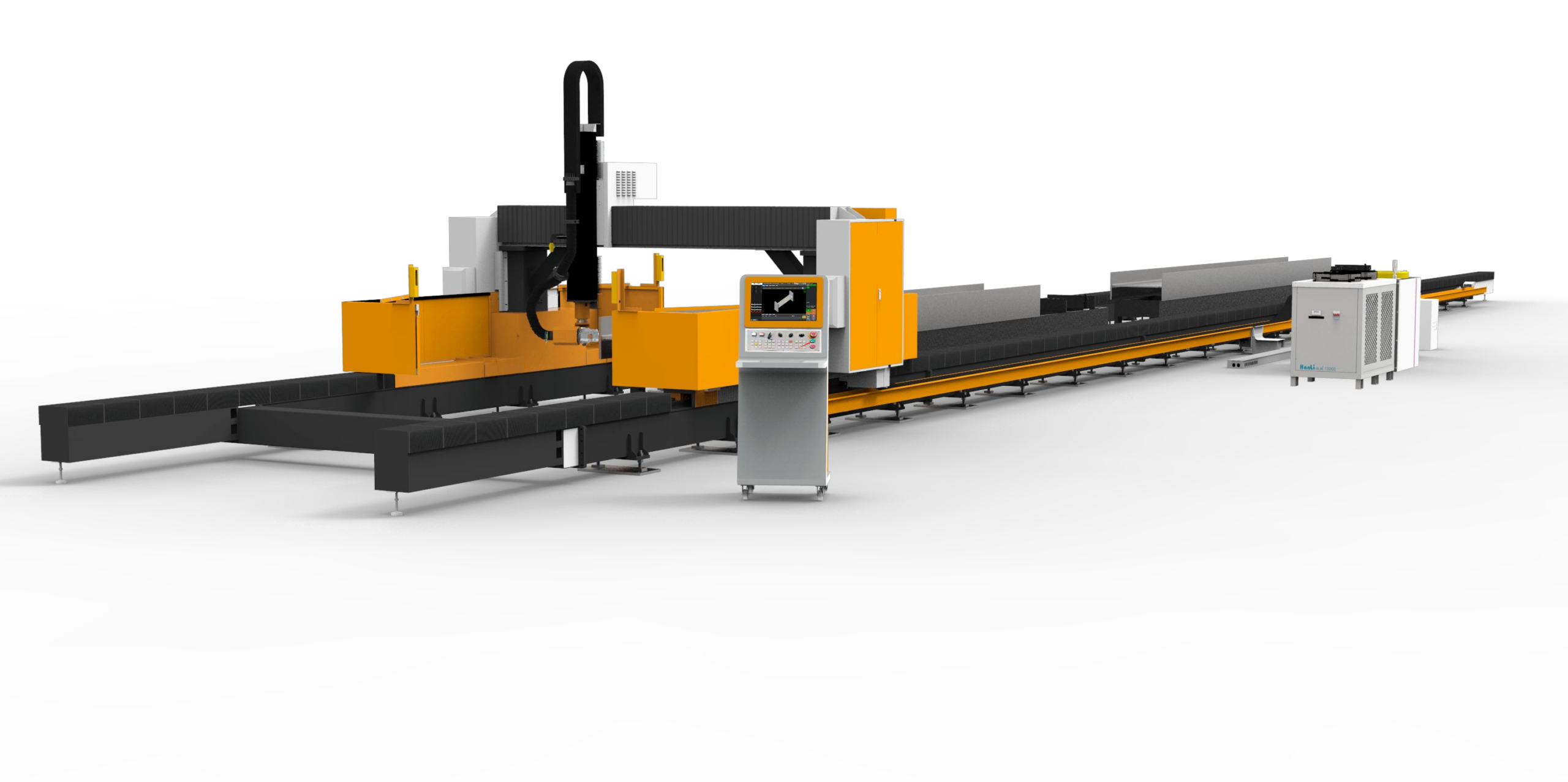
Technical Whitepaper: High-Volume Square Tube Laser Processing for PV Racking Systems
The global transition to utility-scale photovoltaic (PV) installations has created unprecedented demand for high-tolerance, thin-walled square tube structures, typically fabricated from S355JR structural steel or, increasingly, Al6061-T6 for weight-sensitive tracker systems. When production targets exceed 10,000 linear meters per shift, the margin for error in cut quality, dimensional consistency, and end-face perpendicularity collapses to near zero. As a Chief Application Engineer who has spent two decades on the workshop floor, I can state without reservation that the primary failure modes in this sector are not optical or laser-source related; they are mechanical and thermal. For any operation scaling to this volume, the selection of a high volume square tube laser processing for PV racks system must pivot on the machine’s ability to maintain a rigid, stress-relieved kinematic chain under continuous, brutal operation.
1. Severe Workshop Condition Adaptation: The Dust and Heat Load Problem
PV racking production lines are rarely housed in cleanrooms. They sit adjacent to galvanizing baths, press brakes, and welding stations. The ambient atmosphere is laden with zinc particulate, metallic dust, and humidity fluctuations. The laser cutting head and focusing optics are the most vulnerable components. In high-volume cutting of S355JR, the assist gas—typically industrial Nitrogen at a delivery pressure of 1.5 MPa—is not just for ejection; it protects the optics from spatter. However, standard shielding fails when the machine’s internal pressure dynamics fluctuate due to clogged filters from galvanized layer burn-off.
We have resolved this by specifying a positive-pressure enclosure for the cutting head and the rack-and-pinion drive system. The machine’s electrical cabinet must be rated IP54 minimum, with a heat exchanger rather than ambient air fans. In one installation in a Middle Eastern facility, ambient temperatures hit 45°C. The servo drives for the X-axis (longitudinal tube feed) began to derate due to thermal overload. The adaptation required re-routing hydraulic cooling lines to the linear motor stators, ensuring the base structure did not become a heat sink that induced localized expansion.
2. Thermal Expansion Mitigation in the Cutting Zone
Let’s talk physics. When cutting a 100mm x 100mm square tube with a 3mm wall thickness, the laser beam—typically a 6kW to 8kW fiber source operating at a 1070nm wavelength—delivers a power density exceeding 1 MW/cm². The kerf zone reaches temperatures above 2000°C. While the nitrogen jet at 1.2 MPa efficiently evacuates molten material, the heat affected zone (HAZ) on the cut edge induces micro-stresses. The critical issue is the chuck-to-chuck distance. If the front chuck and rear chuck are mounted on a single continuous steel beam, the heat from the cutting process will conduct through the tube and into the chuck jaws, causing the beam to bow.
The mitigation strategy is not just about material selection; it is about geometry. The machine bed must be constructed from stress-relieved, normalized steel plates (typically S275JR) that have been vibration-aged to eliminate residual casting stress. We mandate a “gantry-free” design for the cutting zone where the tube is stationary, and the laser head moves. This allows the thermal load to be distributed. Furthermore, the chuck jaws—which clamp the tube with pneumatic pressures of 0.6 to 0.8 MPa—must be water-cooled. In high-volume runs, the friction of the rotating chuck (for bevel cuts) generates heat. If the jaw temperature rises by 10°C, the coefficient of friction changes, leading to slippage and inconsistent cut lengths. We install thermal sensors on the chuck housing that feed back to the CNC to compensate for the Z-axis focal position shift.
3. Stress-Relieved Bed Stability and the “Creep” Factor
The most insidious issue in high-volume processing is the slow, incremental movement of the machine bed relative to the floor. A 20-ton laser cutting machine, moving a 12-meter tube at 40 m/min acceleration, generates reaction forces of several kilonewtons. If the bed is not bolted to a properly leveled, reinforced concrete foundation (minimum 300mm thick with rebar), the machine will “walk.” This causes the tube to be cut at a slight angle relative to the previous cut, resulting in a step defect on the end face that prevents proper seating in the PV rack’s p-clamp.
We specify a monolithic polymer-concrete bed for these specific high-volume applications. While steel is stiffer, polymer concrete has a damping factor 10 times higher than steel. This absorbs the vibrational energy from the cutting process and the servo-driven roller feeds. Additionally, the guide rails for the Y-axis (cross-cut) must be mounted on a separate, isolated sub-frame that is thermally decoupled from the main bed. This ensures that when the laser head traverses rapidly, the heat generated in the linear bearings does not warp the rail, which would alter the focal point distance by fractions of a millimeter—enough to cause dross on the bottom edge of the cut.
Comparative Analysis: Conventional vs. Laser Processing
To quantify the operational advantage, consider the following data from a recent line audit for a tracker manufacturer processing 4-meter lengths of S355JR (100x100x3mm):
| Parameter | Conventional Mechanical Sawing | Plasma (CNC) | Fiber Laser (8kW) |
|---|---|---|---|
| Cutting Speed (per 4m tube) | 45 seconds (including deburring) | 25 seconds | 12 seconds |
| Kerf Width | 2.5 mm (saw blade loss) | 4.0 mm (wide HAZ) | 0.3 mm |
| End Face Perpendicularity | ±0.5° (blade wear) | ±1.0° (torch angle drift) | ±0.1° (constant) |
| Heat Affected Zone (HAZ) | N/A (mechanical) | 1.5 mm (hardened edge) | <0.1 mm (oxide-free) |
| Secondary Operations (Deburring) | Required (100%) | Required (100%) | None |
| Tooling Wear Cost (per 1000 cuts) | $150 (blade replacement) | $80 (electrodes/nozzles) | $10 (protective lens) |
| Dimensional Repeatability | ±0.3 mm | ±1.0 mm | ±0.05 mm |
The data confirms that while the initial capital expenditure for the laser is higher, the total cost of ownership (TCO) is lower when factoring in the elimination of deburring stations and the reduction in scrap due to thermal distortion. The laser’s ability to cut with Nitrogen at 1.5 MPa leaves a clean, oxide-free edge that is immediately weldable—a critical factor for galvanized steel where plasma cutting would vaporize the zinc coating and cause porosity in subsequent welds.
Operational Parameters for Sustained Output
For a system running three shifts, we set the laser duty cycle at 85% maximum, not 100%. This prevents the resonator from exceeding its thermal threshold. The assist gas delivery system must be sized with a buffer tank of at least 2000 liters to prevent pressure drop during peak cutting bursts. The CNC controller must have a “thermal drift compensation” algorithm that monitors the ambient temperature and adjusts the axis interpolation to correct for the expansion of the tube itself. A 4-meter tube of S355JR will expand by 0.05mm for every 10°C rise in workshop temperature. In a high-volume environment where the cutting machine is near a furnace, this is the difference between a part that fits and a part that is rejected.
B2B Procurement FAQ
Q1: What is the minimum laser power required to maintain high-volume throughput on 3mm wall square tubes without sacrificing edge quality?
For S355JR up to 4mm wall thickness, a 6kW fiber laser is the absolute minimum for sustained production. However, for true high-volume (over 15,000 cuts per day), an 8kW source is recommended. The higher power allows you to increase the Nitrogen pressure to 1.5 MPa and maintain a cutting speed of 8-10 m/min without the need for a second pass. If you are processing Al6061, you must switch to a 4kW source with a different focal length to manage the reflectivity and higher thermal conductivity of aluminum.
Q2: How do we mitigate the risk of thermal distortion on the machine bed when processing long tubes in a non-climate-controlled facility?
You must specify a machine with a dual-frame structure. The outer frame supports the tube loading mechanism, while the inner frame, isolated by rubber dampers, supports only the cutting head and the chuck system. This inner frame must be made of Invar or a similar low-expansion alloy, or it must be actively cooled with a closed-loop chiller that maintains the bed temperature within ±1°C of the ambient baseline. We also recommend installing linear scales for position feedback rather than relying on servo motor encoders, as scales measure actual position regardless of lead screw expansion.
Q3: What specific gas delivery infrastructure is required to avoid downtime in a 24/7 operation?
You cannot rely on a single liquid Nitrogen tank. You need a dual-bank manifold system with automatic switchover. The delivery pressure must be regulated at the machine inlet to 1.2 to 1.5 MPa with a variance of less than 0.1 MPa. The piping must be stainless steel, not copper, to prevent scale contamination of the cutting nozzle. Additionally, install a high-flow regenerative desiccant dryer to ensure the dew point is below -40°C. Moisture in the assist gas is the primary cause of internal optics failure and inconsistent cut edge oxidation.













