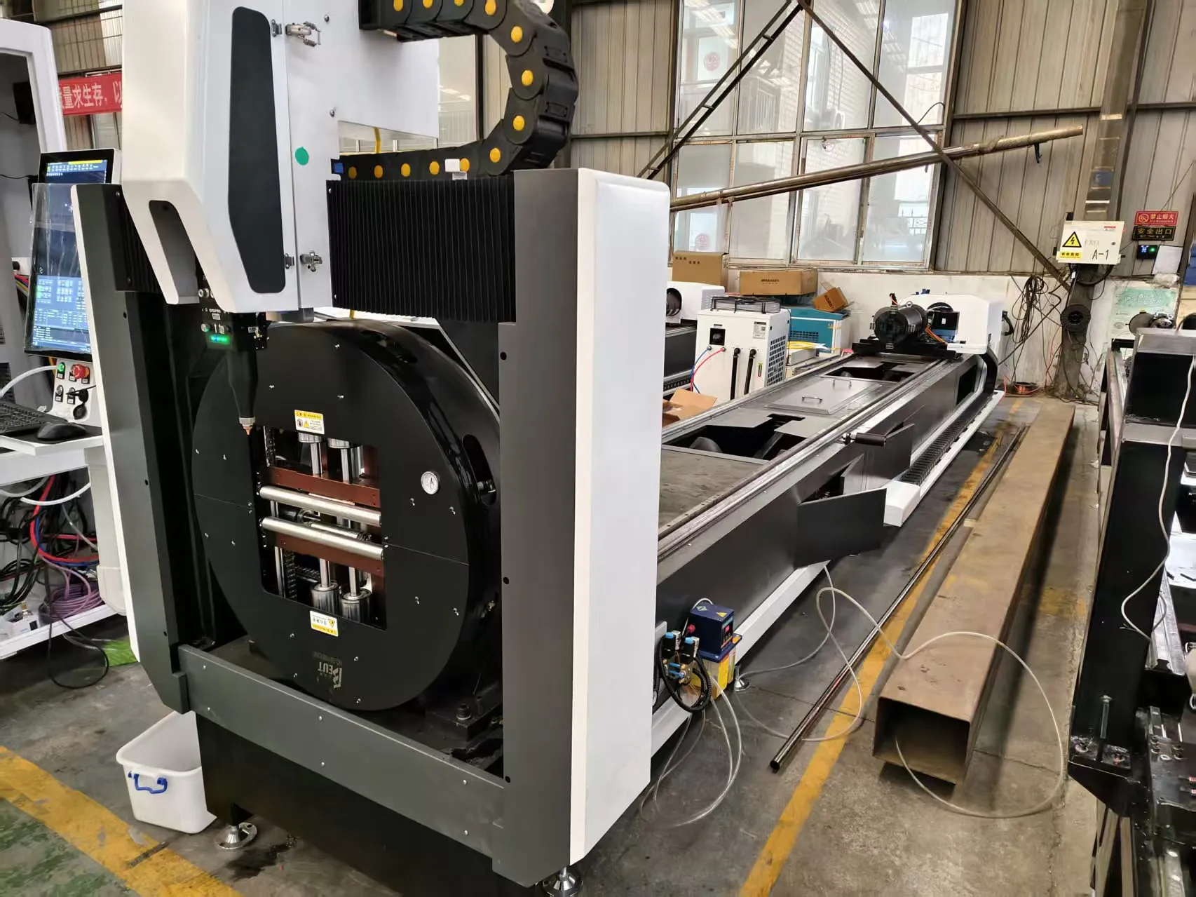
Operational Metallurgy and Structural Dynamics in Solar Tracker Fabrication
The fabrication of solar mounting structures—specifically torque tubes, purlins, and pile caps—has shifted from a low-tolerance structural welding exercise to a high-precision modular assembly process. The bottleneck on the shop floor is no longer the welding speed; it is the hole-making and cut-to-length efficiency of the tube stock. For fabricators running S355JR, SUS304, and Al6061 extrusions, the integration of a high speed punching and cutting laser for solar mounting structures is not a capital upgrade; it is a survival metric against the thermal distortion that plagues traditional plasma and sawing lines.
This analysis dissects the mechanical and thermal realities of deploying fiber laser technology in non-climate-controlled workshops, specifically addressing the trifecta of failure: thermal expansion of the bed, stress relief in the parent metal, and the pneumatic rigidity required to hold thin-wall tubing during high-acceleration punching cycles.
Workshop Environment Reality: Thermal Expansion and Bed Stability
A standard 12-meter tube laser cutting system does not operate in a laboratory vacuum. In summer months, a steel fabrication shed in a low-latitude region can see ambient temperature swings from 18°C at 6:00 AM to 42°C by 2:00 PM. For a 12,000 mm steel bed, the coefficient of thermal expansion (CTE) for mild steel is approximately 11.7 x 10⁻⁶ /°C. A 24°C delta translates to a linear expansion of roughly 3.37 mm across the machine bed length.
If the machine’s absolute encoder reference is established at 6:00 AM, by mid-afternoon, the cutting head is attempting to position holes relative to a bed that has grown 3.37 mm. On a solar pile cap pattern with ±0.5 mm hole-to-hole tolerance, this is a guaranteed scrap event. The solution is not simply a climate-controlled room—that is economically unviable for 12-meter stock. The engineering fix is a stress-relieved, segmented bed design utilizing a central fixed reference block and floating support rails that allow longitudinal expansion without altering the X-axis optical scale position.
Thermal Mitigation Parameters for Bed Design
- Bed Material: Stress-relieved welded steel frame (SR grade) normalized at 600°C post-weld to eliminate residual rolling stresses.
- Rail Mounting: Slotted mounting holes with pre-loaded spring washers allowing 4 mm of longitudinal travel per 3-meter segment.
- Cooling Strategy: Chiller setpoint at 22°C ±0.5°C, with flow rate maintained at 45 L/min for the 6 kW source to prevent focal shift (focus drift of ±0.2 mm per 5°C change in lens temperature).
- Compensation: Real-time thermal compensation via linear glass scales mounted on Invar (CTE ~1.2 x 10⁻⁶ /°C) to decouple measurement from bed expansion.
Punching vs. Cutting: The Duty Cycle and Chuck Dynamics
Solar mounting structures require two distinct operations: high-speed punching of bolt holes (typically 14 mm to 18 mm diameter in 2.0 mm to 3.0 mm wall thickness) and clean cutting of tube ends for mitered joints. The term “punching” in a laser context refers to the pierce-and-move cycle. A conventional CO₂ laser requires 0.8 to 1.2 seconds to pierce 3 mm SUS304. A modern 6 kW fiber laser with a 1.2 mm nozzle and Nitrogen assist at 1.4 MPa can pierce that same thickness in 0.15 seconds using a single pulse burst.
The mechanical challenge is the chuck. A 12-meter tube laser uses a pneumatic self-centering chuck. For thin-wall Al6061 tubing (2.0 mm wall), the clamping pressure must be reduced to 0.4 MPa to 0.6 MPa to prevent ovalization. However, during high-speed punching (acceleration up to 1.5 G), the tube will slip if the chuck pressure is too low. The field solution is a dual-circuit pneumatic system: high pressure (0.9 MPa) for the primary clamping jaws during cutting, and a secondary low-pressure (0.3 MPa) circuit for the rear support steady rest to prevent whipping.
Gas Delivery and Nozzle Geometry for Solar Alloys
Oxygen assist is prohibited for SUS304 and Al6061 due to oxidation and dross formation. Nitrogen (99.999% purity) is mandatory. For 3 mm S355JR, the delivery pressure at the nozzle must be maintained at 1.2 to 1.5 MPa. Below 1.0 MPa, the kerf becomes V-shaped and the cut edge roughness (Ra) exceeds 12.5 µm, which compromises the galvanic corrosion resistance of the subsequent hot-dip zinc coating.
Comparative Technical Data: Legacy Methods vs. Fiber Laser Solution
| Parameter | Conventional Plasma + Saw | Mechanical Punch Press | High-Speed Fiber Laser (6 kW) |
|---|---|---|---|
| Hole Tolerance (mm) | ±1.5 | ±0.3 | ±0.05 |
| Heat Affected Zone (HAZ) | 2.5 – 4.0 mm | 0 mm (mechanical) | 0.1 – 0.3 mm |
| Cycle Time per 12m Tube (20 holes) | 180 – 240 sec | 90 – 120 sec (per setup) | 35 – 50 sec |
| Tooling Changeover | Manual die swap (45 min) | Die set swap (60 min) | Zero (software only) |
| Edge Quality (Ra µm) | 25 – 50 | 12 – 25 (shear) | 3.2 – 6.3 |
| Material Utilization | 92% | 95% | 99.2% (nesting) |
| Distortion Risk (S355JR) | High (thermal) | Medium (mechanical) | Low (controlled energy) |
Stress-Relieved Bed Stability: The Invar and Granite Hybrid Approach
The most overlooked failure mode in solar tube processing is residual stress release during laser cutting. When a 3 mm S355JR tube is cold-formed, the corners contain residual tensile stresses. As the laser cuts a 18 mm hole, the stress field redistributes. If the bed is not rigid enough to hold the tube flat, the tube will bow upward by 1.5 to 3.0 mm between the chuck and the steady rest. This bowing changes the focal distance from the nozzle to the material surface, causing incomplete penetration on the bottom of the tube.
To mitigate this, the bed must incorporate a granite-epoxy composite or a stress-relieved cast iron base with a damping factor of at least 0.03. The steady rest rollers must be polyurethane (Shore A 90) to absorb vibration without marring the Al6061 surface finish. For SUS304, the roller pressure should be set to 0.2 MPa to prevent work hardening at the contact point.
Real-World Parameter Set for 3 mm SUS304 Solar Rail
- Laser Power: 4.5 kW (CW mode)
- Frequency: 5,000 Hz (for piercing), 2,500 Hz (for cutting)
- Duty Cycle: 85% (piercing), 100% (cutting)
- Focus Position: -0.5 mm (below surface)
- Cutting Speed: 4.2 m/min
- Assist Gas: N₂ at 1.5 MPa
- Chuck Pressure: 0.8 MPa (front), 0.4 MPa (rear)
Procurement FAQ: Industrial B2B Sourcing
What is the minimum wall thickness for stable high-speed punching on a fiber laser without deformation?
For Al6061, the minimum stable wall thickness is 1.5 mm with a chuck pressure of 0.3 MPa. For SUS304, the minimum is 1.0 mm, but the cutting speed must be reduced by 30% to avoid heat accumulation that causes ovalization. Below these thresholds, a mandrel or internal support is required.
How does the machine compensate for a 30°C ambient temperature swing in a non-climate-controlled workshop?
Compensation is achieved through a combination of Invar glass scales (CTE 1.2 x 10⁻⁶ /°C) for position feedback and a closed-loop chiller maintaining the laser source at 22°C. The bed itself is mounted on slotted rails allowing 4 mm of longitudinal expansion per 3-meter segment, preventing buckling.
What is the expected duty cycle for a 6 kW source when cutting 3 mm S355JR with 20 holes per 12-meter tube?
The duty cycle is approximately 85% for the laser source and 92% for the chuck clamping cycle. The limiting factor is the piercing time (0.15 sec per hole) and the rapid traverse between holes (1.5 G acceleration). A 20-hole pattern on 12-meter tube is completed in 42 seconds, including load/unload.













