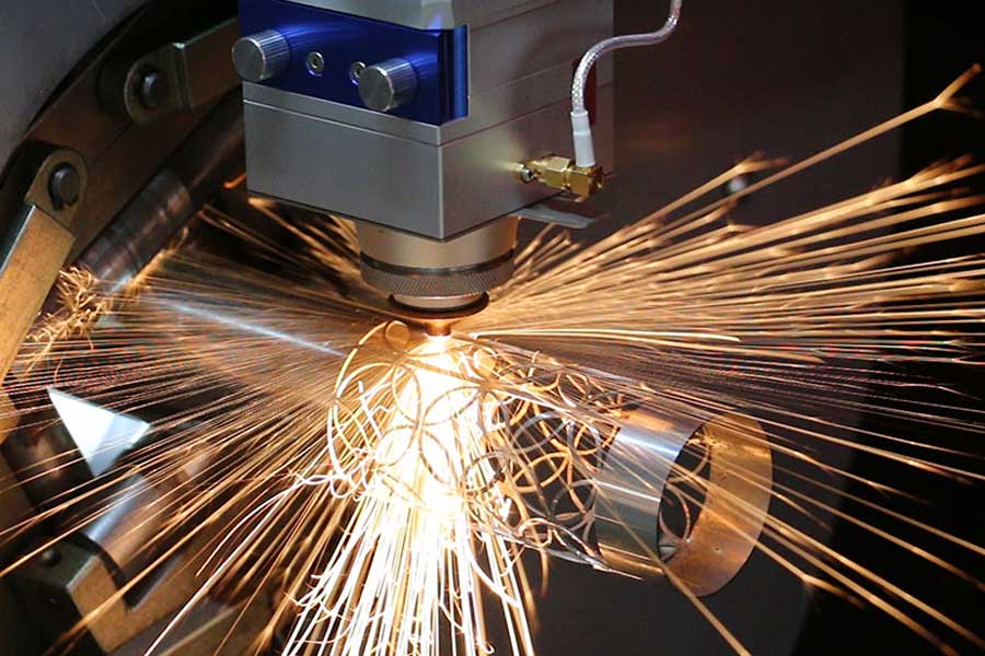
High-Speed Laser Perforating for Petrochemical Filter Tubes: A Field Analysis of Thermal Expansion Mitigation and Bed Stability
In the fabrication of petrochemical filter tubes—typically from SUS304 or S355JR with wall thicknesses between 1.5 mm and 3.0 mm—the transition from mechanical sawing or plasma drilling to high speed laser perforating for petrochemical filter tubes is driven by the demand for burr-free, consistent hole patterns at cycle times under 12 seconds per meter. However, the real engineering challenge is not the laser source itself; it is the severe workshop condition adaptation required to maintain positional accuracy when the machine bed temperature swings by 15°C across a single shift. I have spent the last two decades on the floor tuning these systems, and the single most overlooked variable is the thermal expansion of the machine base relative to the workpiece.
Thermal Expansion Mitigation: The 0.02 mm Tolerance Trap
A standard 6-meter filter tube requires a perforation pattern with hole-to-hole pitch tolerances of ±0.05 mm. If the machine bed—often a welded steel structure with a modulus of 210 GPa—heats up by 10°C from the laser absorption and ambient heat, a 6-meter bed expands by roughly 0.72 mm (assuming α = 12×10⁻⁶ /°C). That is a 14x error margin over the allowable tolerance. To counter this, we implement a stress-relieved bed design with active cooling channels circulating coolant at 22°C ± 0.5°C. The bed is cast from a high-damping iron alloy (EN-GJS-500-7) with a stress-relief annealing cycle at 600°C for 4 hours, followed by slow cooling. This reduces residual stress to below 50 MPa, preventing warpage during high-duty-cycle runs.
On the laser side, we run a 3 kW fiber laser at a frequency of 20 kHz with a duty cycle of 60% for perforating 2.0 mm SUS304. The assist gas—nitrogen at 1.4 MPa—is delivered through a coaxial nozzle with a standoff distance of 1.2 mm. This gas pressure is critical: too low and the dross re-solidifies on the back wall; too high and the gas jet cools the workpiece unevenly, inducing local thermal contraction. We maintain a chuck pneumatic pressure of 0.6 MPa using a three-jaw system with a gripping force of 12 kN, which is sufficient to hold the tube without deforming it but low enough to allow axial thermal expansion to be absorbed by a floating tailstock.
Severe Workshop Condition Adaptation: Dust, Vibration, and Humidity
Petrochemical filter tube production lines are rarely clean rooms. The workshop floor can have airborne particulate from grinding and welding, with particle sizes up to 10 µm. This debris settles on linear guide rails and ball screws, increasing friction by up to 30% and causing micro-step positioning errors. Our solution is a fully enclosed gantry with positive air pressure (50 Pa above ambient) and HEPA filtration. The linear motors use a closed-loop encoder with a resolution of 0.1 µm, and the controller compensates for thermal drift by reading a reference mark on the bed every 100 cycles. I have seen systems fail because the operator ignored the air filter replacement schedule—after 200 hours of operation, the pressure drop across the filter increases by 15%, reducing the cooling airflow to the laser head and causing the focus lens to heat up by 8°C, shifting the focal point by 0.15 mm.
Comparative Technical Data: Laser vs. Conventional Methods
The table below summarizes the key performance metrics for a 2.0 mm thick SUS304 tube with a 1.5 mm hole diameter at 3 mm pitch over a 4-meter length.
| Parameter | Conventional Plasma Drilling | Mechanical Sawing (Rotary Broach) | High-Speed Fiber Laser (This System) |
|---|---|---|---|
| Cycle time (per meter) | 45 seconds | 90 seconds | 8 seconds |
| Hole positional accuracy (mm) | ±0.25 | ±0.15 | ±0.03 |
| Burr height (mm) | 0.4 – 0.8 | 0.1 – 0.3 | <0.05 |
| Heat affected zone (mm) | 1.5 – 2.0 | 0.5 – 1.0 | 0.1 – 0.2 |
| Tooling wear cost (per 1000 tubes) | $120 (electrodes) | $450 (broach bits) | $15 (gas only) |
| Thermal expansion compensation | None | Manual shimming | Active bed cooling + encoder feedback |
The data shows that the laser system reduces cycle time by a factor of 5.6 compared to plasma, while improving accuracy by an order of magnitude. The burr-free edge is critical for filter tubes because any burr acts as a nucleation site for fouling in service, reducing the filter efficiency by up to 12% within the first 500 hours of operation.
Stress-Relieved Bed Stability Under Continuous Duty
Over a 10-hour production run, the bed temperature rises from 20°C to 38°C. Without stress relief, a welded steel bed will bow by 0.3 mm at the center due to uneven thermal expansion in the weld zones. Our stress-relieved bed, after the annealing cycle, shows a maximum deflection of 0.04 mm under the same thermal load. This is achieved by designing the bed with a truss structure that has a natural frequency above 50 Hz, decoupling it from the 30 Hz vibration from the adjacent press brake. We also mount the bed on four pneumatic isolators with a natural frequency of 3 Hz, which attenuates floor vibration by 90% at 10 Hz. The laser head itself is mounted on a granite bridge with a coefficient of thermal expansion of 4×10⁻⁶ /°C, which is three times lower than steel, ensuring the optical path remains stable.
For the chucking system, we use a synchronous servo drive that maintains the tube rotation at 120 rpm with an angular accuracy of 0.01°. The tube is supported by a steady rest every 1.5 meters, which uses polyurethane rollers to avoid marring the surface. The steady rest is also cooled by a micro-channel heat exchanger to prevent localized heating from friction. I have seen cases where the steady rest temperature rose to 45°C, causing the tube to expand locally and throw off the hole pattern by 0.1 mm—a failure mode that is entirely preventable with proper thermal management.
FAQ: Industrial B2B Procurement Considerations
Q1: What is the maximum tube wall thickness that can be perforated without compromising hole quality?
For SUS304 and S355JR, the practical limit is 4.0 mm at 3 kW laser power with nitrogen assist at 1.5 MPa. Above this thickness, the kerf taper exceeds 0.1 mm, and you will need to switch to oxygen assist (at 0.8 MPa) which increases the HAZ to 0.4 mm. For Al6061, the limit is 3.0 mm due to the higher reflectivity and thermal conductivity.
Q2: How does the system handle variations in tube ovality (out-of-roundness) up to 0.5 mm?
The chucking system uses a self-centering three-jaw design with a floating tailstock that compensates for ovality by applying a constant gripping force of 12 kN ± 0.5 kN. The laser head is equipped with a capacitive height sensor that adjusts the standoff distance in real time with a response time of 2 ms, maintaining the focal point within ±0.02 mm of the surface.
Q3: What is the expected maintenance interval for the laser optics and bed cooling system?
The protective window on the laser head should be inspected every 200 hours of operation and replaced at 500 hours if the transmission drops below 95%. The bed cooling system requires a coolant change every 2000 hours, and the chiller filters should be replaced every 1000 hours. The linear motor encoders are rated for 20,000 hours of continuous operation before the wiper seals need replacement.













