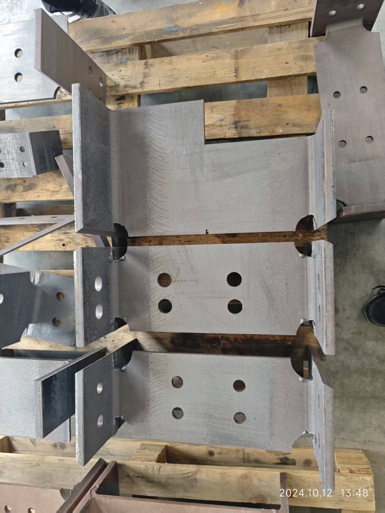
Technical Assessment: Heavy Duty Tube Laser Cutting for Automotive Chassis Fabrication
The transition from mechanical sawing and plasma cutting to heavy duty tube laser cutting for automotive chassis fabrication is not a trend; it is a direct response to yield loss and post-processing bottlenecks. When I audit a Tier-1 or Tier-2 chassis supplier, I am not looking at marketing brochures. I am looking at the spindle runout on the saw, the dross adhesion on the plasma torch, and the labor hours spent on deburring. The laser replaces these variables with a controlled photonic process, but only if the machine is treated as a high-precision mechanical system, not a magic box. The specific challenge for chassis rails, crossmembers, and roll cages lies in the material: S355JR and S460ML structural steel, often with a wall thickness between 6 mm and 15 mm, and a yield strength that demands consistent heat input management.
Let’s address the physics first. For a 10 mm S355JR tube, you are typically running a 4 kW to 6 kW fiber laser source. The cutting head must maintain a focal point tolerance of ±0.1 mm. The critical parameter is not just the average power, but the pulse frequency and duty cycle. For piercing thick-wall chassis tube, I recommend a pulse frequency of 500 Hz to 1000 Hz with a duty cycle starting at 10% to prevent the formation of a plasma plume that can back-reflect into the optics. Once the pierce is complete, switch to continuous wave (CW) operation. The assist gas is where most shops fail. For clean, oxide-free edges on structural steel, you need nitrogen at a delivery pressure of 1.2 to 1.5 MPa. If you drop below 1.0 MPa, you will see striation marks deepen and a nitride layer form that requires secondary grinding before welding. For thicker sections where oxidation is acceptable for non-critical brackets, oxygen at 0.4 to 0.6 MPa increases speed by 15%, but you must accept a hardened edge that is difficult to weld without pre-heat.
After-Sales Troubleshooting: The Real-World Failure Modes
I have seen too many production managers blame the laser source when the issue is purely mechanical. The most common failure mode in heavy-duty chassis cutting is not the resonator; it is the chuck and the guide rings. When you are handling a 12-meter long, 200 mm diameter tube, the weight alone causes deflection. If your pneumatic chuck pressure is not set correctly, you get micro-slip. For a 200 mm OD tube, you need a clamping pressure of 2.5 to 3.0 MPa to prevent torsional wind-up. If you see a “spiral cut” or a taper at the end of the cut, it is not the laser. It is the chuck slipping by 0.5 degrees during the rotation cycle. Check the collet wear. If the serrated inserts are worn beyond 0.2 mm, they lose their grip on the mill scale of the S355JR. You will see this as an oval cut profile.
Another frequent issue is the focus lens contamination. In a high-volume chassis shop, the environment is full of oil mist and metallic dust. If your protective window (cover glass) is not purged with clean, dry air at a minimum of 0.6 MPa, you will get a micro-pinhole burn-through within 8 hours of operation. The symptom is a sudden drop in cut speed capability. The operator will increase power to compensate, which then causes the lens to heat up and expand, shifting the focal point. This is a cascading failure. My rule of thumb: if you are cutting 10 mm wall thickness, you should be replacing the protective window every 40 hours of runtime, not when it fails. The cost of a window is negligible compared to the cost of scrapping a chassis side rail that is 2 meters long.
Consumables Lifecycle Management and Preventive Maintenance
Let me give you a specific maintenance matrix that I implement on the floor. The cutting nozzle is your primary consumable. For a 6 kW laser cutting 10 mm steel, you need a nozzle diameter of 3.0 mm to 3.5 mm. The nozzle orifice is the most sensitive component. If the orifice becomes elliptical due to a crash or spatter, the gas flow becomes turbulent. This turbulence creates a venturi effect that sucks molten metal back up into the kerf, causing what we call “burn-back” on the bottom edge. You must inspect the nozzle with a 10x magnifying glass at every shift change. The lifespan of a copper nozzle at this power level is roughly 200 hours, but only if you maintain the correct standoff distance (typically 0.8 mm to 1.2 mm). If you are using a capacitive height sensor, ensure it is calibrated daily against a known flat surface. A drift of 0.3 mm in standoff will ruin the cut edge geometry.
Regarding the laser source itself, the fiber delivery cable is a weak point. In a heavy-duty environment, the cable is constantly flexing as the gantry moves. I recommend a preventive maintenance schedule that includes checking the fiber connector end-face for contamination every 500 hours. Use a fiber inspection scope. If you see any dark spots, clean with a dry, lint-free wipe and isopropyl alcohol. Do not use compressed air. The cooling system is your next priority. The deionized water must have a conductivity below 5 µS/cm. If the conductivity rises, you get electrolysis inside the laser cavity, which degrades the diodes. I have seen shops lose 20% of their diode efficiency in six months because they ignored the resin filter. Change the resin filter every 3000 hours, and check the glycol concentration to prevent algae growth.
Comparative Analysis: Legacy vs. Laser Systems
To quantify the operational shift, consider the following data from a recent audit of a commercial vehicle chassis manufacturer. They were previously using a band saw and plasma arc. The numbers below reflect a batch size of 500 pieces of 100 mm x 100 mm x 8 mm S355JR square tube, cut to 2-meter lengths with hole features.
| Parameter | Conventional (Band Saw + Plasma) | Fiber Laser (6kW) | Delta / Impact |
|---|---|---|---|
| Cutting Speed (per piece) | 4.5 minutes (saw) + 2.5 min (plasma holes) | 1.8 minutes (all operations) | 55% reduction in cycle time |
| Kerf Width | 3.0 mm (saw) / 4.5 mm (plasma) | 0.3 mm | Material savings of 2.5 kg per 100 pieces |
| Edge Quality (Ra) | 12.5 µm (requires machining) | 3.2 µm (ready for welding) | Eliminates secondary deburring station |
| Heat Affected Zone (HAZ) | 2.5 mm (plasma) – requires edge grinding | 0.2 mm | Preserves S355JR yield strength at edge |
| Consumable Cost per Meter | $0.85 (blade wear + electrode) | $0.30 (nozzle + gas) | 65% reduction in consumable OPEX |
| Setup Changeover Time | 25 minutes (tooling change) | 4 minutes (program recall) | Enables Just-In-Time production |
The data confirms that the laser is not just faster; it changes the metallurgical outcome. The narrow HAZ means you are welding on virgin base material, not on a recast layer that is prone to cracking. However, this efficiency is only realized if the preventive maintenance schedule is enforced. I have seen shops with identical machines produce wildly different results. The difference is always the discipline of the maintenance crew.
Operational Protocols for Longevity
For the pneumatic system, verify that your air compressor provides a dew point of -20°C. Moisture in the assist gas line will cause micro-cracks in the cut edge. Install a desiccant dryer immediately after the compressor, not at the machine. The distance matters. If the pipe is long, you will get condensation. Also, check the gas pressure at the nozzle, not at the regulator. I recommend installing a pressure transducer right at the cutting head. The pressure drop across the swivel joint can be 0.2 MPa, which is significant. For the chuck, lubricate the guide rails with a lithium-based grease every 200 hours. Do not use oil; it will attract dust and create a grinding paste that wears the linear guides.
Finally, monitor the assist gas consumption. If you are using nitrogen at 1.5 MPa, a 6 kW laser will consume roughly 40 m³/hour. If your consumption spikes by 20%, you have a leak in the swivel or a damaged nozzle. Leaks are not just a cost issue; they cause pressure fluctuations that ruin the cut edge. Implement a daily log sheet where the operator records the gas pressure, the lens condition, and the nozzle diameter. This data is your early warning system. When you see a trend of decreasing cut speed at the same power settings, you know the optics are degrading. Do not wait for a catastrophic failure. Replace the lens assembly when the cut speed drops by 5% from baseline, not when the machine alarms out. This proactive approach is the difference between a machine that runs for 10 years and one that requires a major overhaul in year three.
Frequently Asked Questions (Industrial Procurement)
Q1: What is the maximum wall thickness we can cut on a heavy-duty tube laser for chassis frames without compromising edge quality?
With a 6 kW fiber laser, you can reliably cut up to 20 mm wall thickness in S355JR using nitrogen assist gas, but you will be limited to a cutting speed of approximately 0.8 m/min. For optimal productivity and edge quality (Ra < 3.2 µm) for welding, we recommend staying within the 6 mm to 15 mm range. Above 15 mm, the process becomes slower than plasma, and you must evaluate the cost of nitrogen against the savings in secondary machining. For 20 mm, you may need to switch to oxygen to maintain speed, accepting a slightly oxidized edge.
Q2: How do we calculate the true Return on Investment (ROI) when replacing our current sawing and drilling operation?
You must calculate the “cost per finished meter” including labor, consumables, and rework. Do not just compare cycle times. Factor in the elimination of the deburring station (typically 1 operator per shift), the reduction in material waste from kerf loss (0.3 mm vs 3.0 mm), and the reduction in WIP (Work In Progress) inventory because setup times drop from 25 minutes to 4 minutes. In most audits, the laser pays back in 2.5 to 3.5 years based on a single shift operation. If you run two shifts, this drops to under 2 years.
Q3: What specific preventive maintenance must we perform to ensure the laser tube cutter maintains its accuracy for chassis components?
Three critical items. First, verify the chuck clamping pressure daily (target 2.5 – 3.0 MPa) and inspect the collet inserts for wear every 200 hours. Second, check the focus lens and protective window condition every shift; replace the window every 40 hours of cutting time. Third, monitor the deionized water conductivity in the laser resonator weekly; it must remain below 5 µS/cm. Additionally, calibrate the capacitive height sensor against a known flat surface every 40 hours to maintain the correct standoff distance. These steps prevent the most common causes of scrap: oval cuts, taper, and burn-back.













