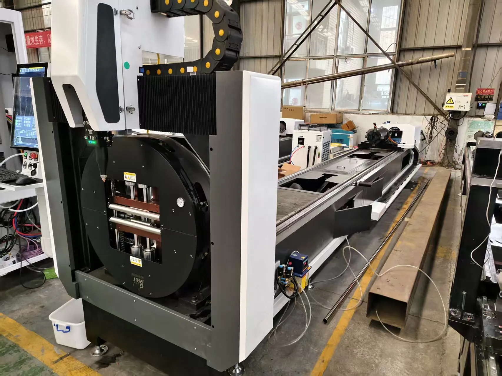
System Integration for Heavy-Duty Axle Housing Fabrication: Engineering Analysis of Fiber Laser Tube Processing
Fabricating heavy truck axle housings from raw tube stock demands a radical departure from standard structural tube processing. The wall thicknesses involved—typically 10 mm to 16 mm in high-strength low-alloy steel—combined with the geometric distortion inherent to welding a banjo housing onto a seamless tube, create a dimensional nightmare. When a shop foreman asks why their existing plasma table or band saw is producing axle tubes that require 4 mm of post-weld machining on the spindle shoulder, the answer usually lies in the heat-affected zone (HAZ) and the lack of stress-relieved bed stability in the cutting machine itself. For operations moving toward a dedicated fiber laser pipe cutting machine for heavy truck axle housing, the conversation must shift from “cut speed” to “thermal equilibrium and torsional rigidity.”
This analysis dissects the specific engineering adaptations required for a fiber laser system to survive and thrive in a heavy fabrication workshop where ambient temperatures swing from 5°C in winter to 42°C in summer, and where the floor vibrates from 50-ton presses operating 20 meters away.
Workshop Condition Adaptation: The Vibration and Dust Factor
Heavy truck axle production is not clean-room work. The environment is saturated with airborne abrasive dust from grinding operations and fine metallic particulate from welding fume extraction. A standard IP54-rated laser head will fail within 800 hours of operation in this atmosphere. The specific adaptation required is a positive pressure, dual-stage filtration system that maintains 0.3 MPa of clean air overpressure inside the optical compartment. The protective window (typically a 50 mm diameter fused silica with anti-reflective coating for 1070 nm wavelength) must be purged with instrument-grade nitrogen at 0.2 MPa to prevent spatter adhesion.
Floor vibration is the silent killer of cut quality. When a 6-meter length of S355JR tube with a 180 mm outer diameter and 12 mm wall is rotating at 60 RPM, any external vibration above 0.5 mm/s RMS will cause striation patterns on the cut face that exceed 50 microns in depth. The machine bed must be isolated using active pneumatic vibration isolators tuned to a natural frequency below 8 Hz. The concrete foundation block—minimum 1.2 meters thick and reinforced with rebar—must be physically separated from the main factory floor by a 50 mm expansion joint filled with closed-cell polyethylene foam.
Thermal Expansion Mitigation: The 12-Meter Problem
A standard axle housing tube for a Class 8 truck is 2.4 meters long, but the raw stock often arrives in 12-meter lengths. A 12-meter steel tube experiences a linear expansion of approximately 1.44 mm for every 10°C temperature change (coefficient of thermal expansion for steel: 12 x 10^-6 /°C). If the machine’s linear axis (typically a rack and pinion drive with a helical gear) is not thermally compensated, the positioning accuracy at the far end of the tube will drift by 0.5 mm to 1.2 mm over a single shift.
The solution is a dual-pronged approach. First, the machine bed must be constructed from a single, stress-relieved weldment that has undergone vibratory stress relief (VSR) at 180 Hz for 45 minutes, followed by a 24-hour natural aging process. Second, the CNC must incorporate real-time thermal compensation using 4 PT100 RTD sensors embedded along the linear guide rails. The control software applies a correction factor of 0.012 mm per meter per degree Celsius deviation from 20°C.
For the rotary axis, the chuck pneumatic pressure must be precisely regulated. Clamping a 180 mm diameter, 12 mm wall tube requires a minimum of 0.6 MPa to prevent slippage during high-torque acceleration (0.8 G). However, exceeding 0.9 MPa on a thin-wall tube (8 mm) will cause ovality deformation of up to 0.3 mm. The system must use a proportional pressure regulator with closed-loop feedback from a strain gauge on the chuck jaw.
Stress-Relieved Bed Stability: The Foundation of Accuracy
The bed of a fiber laser tube cutter for axle housings is not a simple weldment. It is a precision structure that must maintain 0.05 mm/m straightness over a 12-meter span under a 1,500 kg load. The material of choice is a normalized, high-carbon cast iron (GGG-60) or a polymer concrete composite. Polymer concrete offers a damping factor 10 times higher than steel, reducing harmonic resonance during cutting.
The bed must be stress-relieved in three stages: rough machining, semi-finish machining, and final finish machining. Between each stage, the bed undergoes thermal cycling from -20°C to 60°C for 48 hours. This ensures that the residual stresses from casting and welding are fully dissipated. Without this, the bed will warp by 0.2 mm to 0.5 mm over the first 6 months of operation, rendering the machine incapable of holding the ±0.1 mm tolerance required for axle spindle bores.
Comparative Technical Data: Legacy Methods vs. Fiber Laser
The following table compares the operational parameters of conventional plasma cutting, mechanical sawing, and the specific fiber laser solution for heavy truck axle housing tube processing. Data is based on 12 mm wall S355JR steel tube, 180 mm OD.
| Parameter | Conventional Plasma | Mechanical Sawing (Band/Circular) | Fiber Laser (1.5 kW – 3 kW) |
|---|---|---|---|
| Cutting Speed (12 mm wall) | 1.2 – 1.8 m/min | 0.3 – 0.6 m/min | 2.5 – 4.0 m/min |
| Heat Affected Zone (HAZ) | 1.5 – 3.0 mm | 0.1 – 0.3 mm (mechanical) | 0.05 – 0.15 mm |
| Kerf Width | 2.5 – 4.0 mm | 3.0 – 5.0 mm | 0.2 – 0.5 mm |
| Dimensional Tolerance (per 2.4 m) | ±0.8 mm | ±0.5 mm | ±0.1 mm |
| Post-Cut Machining Allowance | 2.0 – 3.0 mm | 1.0 – 1.5 mm | 0.1 – 0.3 mm |
| Assist Gas (Pressure/Consumption) | O2 / 0.8 MPa / 25 m³/h | N/A (coolant required) | N2 / 1.4 MPa / 18 m³/h |
| Duty Cycle (Continuous) | 60% @ 200A | 100% (blade wear) | 100% (fiber source) |
| Ovality Deformation (after clamping) | 0.4 – 0.8 mm | 0.2 – 0.5 mm | 0.05 – 0.12 mm |
Process Parameters for Specific Alloys
Axle housings are not always mild steel. For high-performance or electric truck applications, materials like SUS304 (stainless steel) or Al6061-T6 (aluminum) are increasingly common. The fiber laser parameters must be adjusted accordingly.
- S355JR (Mild Steel, 12 mm): Laser power 2.5 kW, frequency 5,000 Hz, duty cycle 80%, cutting speed 3.2 m/min, focus position -1.5 mm, nitrogen assist gas at 1.4 MPa. The oxygen content in the assist gas must be below 50 ppm to prevent oxidation of the cut face.
- SUS304 (Stainless Steel, 10 mm): Laser power 3.0 kW, frequency 8,000 Hz, duty cycle 100%, cutting speed 2.0 m/min, focus position -2.0 mm, nitrogen assist gas at 1.5 MPa. The high frequency reduces dross adhesion on the bottom edge.
- Al6061-T6 (Aluminum, 8 mm): Laser power 2.0 kW, frequency 3,000 Hz, duty cycle 70%, cutting speed 4.5 m/min, focus position -0.5 mm, nitrogen assist gas at 1.2 MPa. The lower duty cycle prevents heat buildup that would cause micro-cracking in the HAZ.
The chuck clamping pressure for aluminum must be reduced to 0.4 MPa to prevent jaw indentation. For stainless steel, the pressure can remain at 0.7 MPa, but the chuck jaws must be fitted with polyurethane pads to prevent galling.
FAQ: Industrial B2B Procurement
What is the maximum wall thickness a fiber laser can cut for heavy truck axle housings?
For a 3 kW single-mode fiber laser, the maximum clean-cut thickness in S355JR is 16 mm with nitrogen assist gas at 1.5 MPa. Beyond 16 mm, the cutting speed drops below 1.0 m/min and dross formation becomes problematic. For 20 mm wall, a 4 kW or 6 kW source is required, but the HAZ widens to 0.3 mm, necessitating a post-cut stress relief if the axle housing is subject to fatigue loading.
How does thermal expansion affect the positioning accuracy of a 12-meter tube laser?
Without compensation, a 10°C temperature rise causes a 1.44 mm elongation over 12 meters. This translates directly to a 1.44 mm positioning error at the far end of the tube. The machine must use linear encoders with a resolution of 0.1 micron and a thermal compensation algorithm that adjusts the commanded position based on real-time RTD data. The residual error after compensation should be less than 0.05 mm.
What is the required pneumatic clamping pressure for thin-wall axle tubes to avoid ovality?
For an 8 mm wall tube with a 180 mm OD, the clamping pressure must not exceed 0.5 MPa. At 0.6 MPa, the tube ovality increases to 0.25 mm, which exceeds the tolerance for most axle spindle bores. The system should use a proportional valve with a pressure sensor and a closed-loop control that adjusts the pressure based on the tube’s wall thickness input into the CNC.













