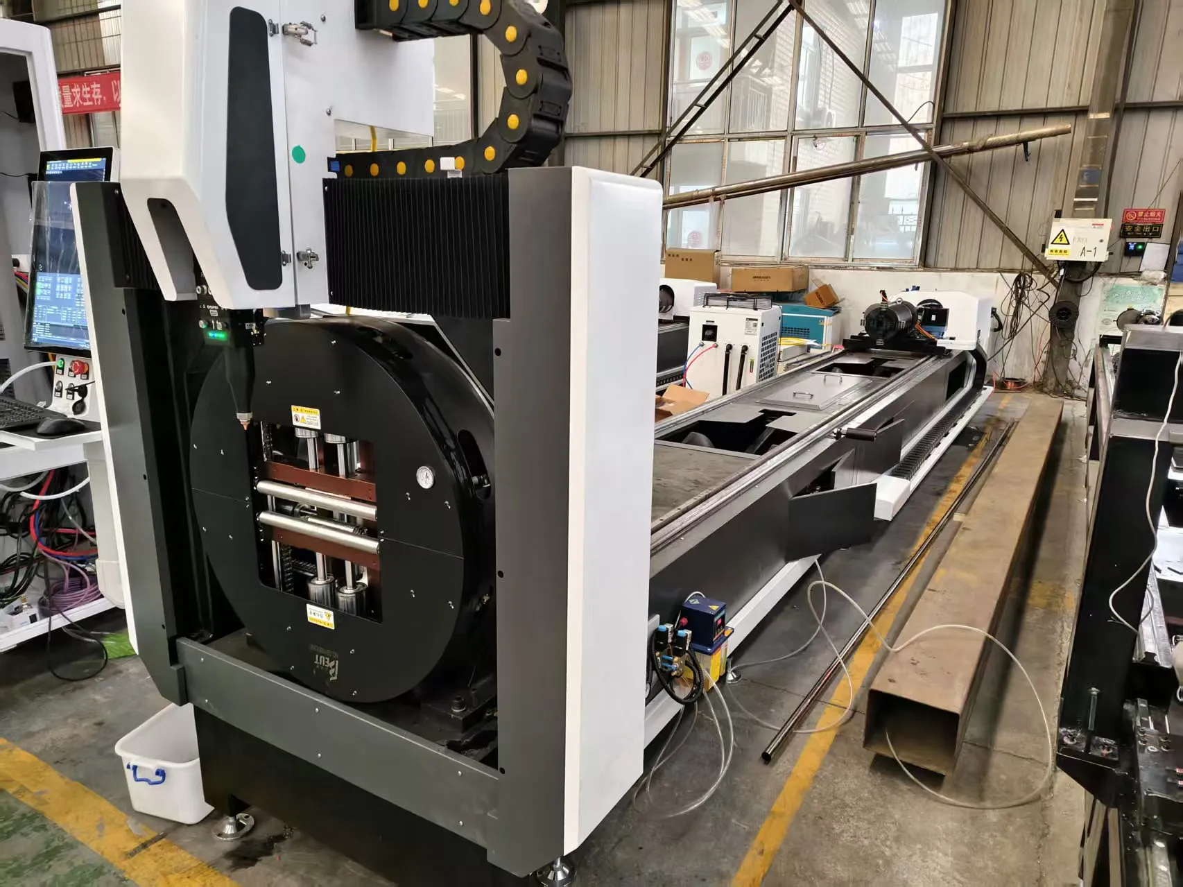
Metallurgical and Mechanical Considerations for Excavator Cylinder Support Fabrication
The structural support brackets for excavator hydraulic cylinders are not merely bent plates; they are fatigue-rated components subjected to cyclic loading in the 20-35 MPa range, often with peak shock loads exceeding 60 MPa during bucket impact. When we move from traditional oxy-fuel or plasma cutting to a dedicated fiber laser pipe cutting for excavator hydraulic cylinder support system, we are fundamentally altering the heat-affected zone (HAZ) profile and the residual stress distribution. For S355JR or higher-grade S460ML steel, a 6 kW to 8 kW fiber laser source operating at a wavelength of 1070 nm delivers a power density exceeding 10^6 W/cm². This allows for a kerf width reduction from 3.5 mm (plasma) down to 0.8 mm, which directly translates to a reduction in material waste per support arm—typically saving 1.2 kg of steel per component on a 200 mm diameter tube with 12 mm wall thickness.
The critical issue on the shop floor is not the cutting speed—which easily reaches 4.5 m/min on 10 mm wall thickness—but the management of the dross and the micro-hardness of the cut edge. With nitrogen as an assist gas at a delivery pressure of 1.5 MPa, we achieve a completely oxide-free edge. However, this requires absolute gas purity (99.999% N2). If a shop attempts to use standard industrial nitrogen at 99.5% purity, the residual oxygen causes exothermic reactions that increase the HAZ depth from 0.1 mm to 0.4 mm, leading to premature cracking at the weld joint where the support meets the cylinder barrel. This is the first diagnostic check we perform during after-sales troubleshooting: verify the gas purity log, not just the laser alignment.
After-Sales Troubleshooting: The Chuck and Collision Axis
In the field, the most frequent failure mode we encounter is not the resonator, but the mechanical chuck system. For excavator supports, we are typically handling 3-meter to 6-meter tubes with a mass of up to 500 kg. The pneumatic clamping pressure must be regulated precisely between 0.6 MPa and 0.8 MPa. If the pressure drifts above 0.85 MPa, we observe micro-deformation of the tube cross-section, causing an ovality error of 0.5 mm. This error propagates through the cutting head, resulting in a focal point shift that produces a taper angle of 2 degrees on the cut face. Conversely, if pressure drops below 0.5 MPa, the tube slips during the rapid traverse (G0 moves at 60 m/min), causing the laser head to crash into the material.
When we perform remote diagnostics on a malfunctioning machine, the first data we pull is the chuck pressure curve over the last 24 hours. We look for pressure decay rates exceeding 0.02 MPa/min, which indicates a leaking rotary union or a worn seal in the chuck cylinder. A common oversight is the lubrication schedule for the ball screw drive on the Z-axis. In a dusty excavator fabrication environment, standard lithium grease becomes contaminated with iron fines, increasing the friction coefficient. This leads to the servo motor drawing higher current, which we can spot in the drive alarm logs. The preventive maintenance fix is straightforward: switch to a synthetic grease with a dropping point above 260°C and apply it at 500-hour intervals, not the manufacturer’s standard 1000-hour interval, given the abrasive environment.
Consumables Lifecycle Management and Gas Delivery Metrics
Let us analyze the consumables cost matrix. A standard cutting head uses a 38 mm diameter focal lens (typically ZnSe for CO2, but for fiber, we use a pure quartz lens or a protective cover glass). For fiber lasers, the protective window is the primary consumable. In a high-volume production environment cutting Al6061 or SUS304 supports, the protective window has a lifespan of approximately 40 hours of continuous operation. However, if the shop is cutting galvanized or painted pipe (common in refurbished excavator parts), zinc vapor condenses on the window, reducing transmission efficiency by 15% within 10 hours. This is detectable by a sudden increase in cutting pressure required to maintain the same edge quality.
We must also discuss the nozzle gap control. For this application, we recommend a capacitive height sensor with a gap setpoint of 0.8 mm. If the gap increases to 1.2 mm, the assist gas jet expands, losing its coherent core velocity. The result is a ragged edge on the lower side of the pipe. The troubleshooting protocol involves checking the nozzle condition—a slight spatter build-up at the nozzle exit (a 2 mm diameter orifice) will disrupt the gas flow. We instruct maintenance crews to inspect the nozzle after every 8 hours of runtime and replace it if the orifice shows any elliptical wear. The cost of a nozzle (approx. $15) is negligible compared to the cost of scrapping a $200 hydraulic cylinder support due to a faulty cut.
Comparative Analysis: Laser vs. Conventional Sawing/Plasma
| Parameter | Mechanical Sawing (Band Saw) | Plasma Arc Cutting | Fiber Laser (6kW-8kW) |
|---|---|---|---|
| Kerf Width (12mm wall) | 3.0 – 4.0 mm | 3.5 – 5.0 mm | 0.8 – 1.0 mm |
| HAZ Depth (S355JR) | 0.5 mm (work hardening) | 1.5 – 2.0 mm | 0.1 – 0.2 mm |
| Cutting Speed (10mm wall) | 0.2 m/min | 1.5 m/min | 4.5 – 6.0 m/min |
| Edge Squareness Tolerance | ±1.0 degree | ±3.0 degrees | ±0.5 degrees |
| Assist Gas Consumption | N/A (no gas) | O2 at 0.8 MPa (high flow) | N2 at 1.2-1.5 MPa (pulsed) |
| Dross Formation | Minimal (mechanical burr) | Heavy, requires grinding | Minimal, often self-ejecting |
| Setup Time (per batch of 50) | 45 minutes (tooling change) | 20 minutes (consumable check) | 5 minutes (program recall) |
| Surface Roughness (Ra) | 6.3 µm | 12.5 µm | 3.2 µm |
The data above illustrates why the laser solution dominates for this specific application. The reduction in HAZ is critical because the support bracket is often welded directly to the cylinder barrel. A plasma-cut edge with a 2 mm HAZ will have a martensitic structure that is brittle. When the excavator operates in cold climates (-20°C), this brittle layer is prone to cracking under impact. The laser cut edge, with its minimal HAZ, retains the ductile properties of the base metal, ensuring the weld joint integrity.
Preventive Maintenance Protocols for the Fiber Delivery System
The fiber optic cable is the “Achilles heel” of the system. In a vibrating environment (near a press brake or a shot blasting machine), the fiber can suffer from micro-bending losses. We implement a preventive maintenance check using an Optical Time-Domain Reflectometer (OTDR) every 500 operational hours. We look for attenuation spikes greater than 0.1 dB at any point along the 20-meter delivery cable. If we detect a spike, we do not attempt to splice; we replace the entire cable section. The cost of downtime for a cable failure during a production run is roughly $500 per hour in lost output, versus the $2,000 cost of a new cable. The math is simple.
Another critical preventive measure is the cooling water conductivity. The laser resonator requires deionized water with a conductivity below 5 µS/cm. In many excavator plants, the water supply is hard water. If the deionization resin is not replaced quarterly, the conductivity rises, leading to electrolysis inside the copper optics block. This manifests as a gradual power drop—from 6 kW to 5.2 kW over a month—which operators often mistake for a resonator fault. The troubleshooting step is to check the water conductivity meter daily and log it. If conductivity exceeds 8 µS/cm, we immediately shut down and replace the resin, avoiding a $15,000 repair bill for the resonator diode stack.
Finally, we address the cutting program parameters. For a typical excavator support with a 120 mm diameter and 10 mm wall thickness, we recommend a pulse frequency of 5 kHz with a 90% duty cycle for the roughing pass, and a 10 kHz frequency with a 50% duty cycle for the finishing pass on the critical weld bevel area. This reduces the thermal load on the internal support ribs, preventing distortion. The operator must also verify the focus position; for this material thickness, a focus position of -2.0 mm below the surface is optimal. A deviation of +0.5 mm will result in a positive taper, making the part unsuitable for the subsequent robotic welding operation.
FAQ: Industrial Procurement and Operational Queries
Q1: What is the typical payback period for a fiber laser pipe cutting machine when switching from plasma for excavator cylinder supports?
Based on our field data, if you are processing over 1,500 tons of S355JR pipe annually, the payback period is between 18 and 24 months. This calculation includes the consumable savings (no grinding discs, fewer gas cylinders), the reduction in rework (from 8% down to 1.5%), and the labor cost reduction (one operator can manage two laser machines versus one plasma machine). The increase in throughput—from 1.5 m/min to 5 m/min—directly impacts the bottleneck in the welding cell.
Q2: How do we handle the cutting of pre-galvanized or painted pipe for hydraulic supports without damaging the laser optics?
We strongly advise against cutting coated materials without a pre-cleaning step. The zinc vapor will deposit on the protective window, causing a “frosting” effect that reduces beam quality. If you must cut coated pipe, we recommend installing a specialized “anti-spatter” nozzle and increasing the protective window inspection frequency to every 4 hours. Alternatively, use a sacrificial Mylar film on the window, which costs $2 and can be replaced in 30 seconds, protecting the $200 quartz lens underneath.
Q3: What is the recommended maintenance schedule for the pneumatic chuck system to ensure consistent clamping force?
We implement a 2,000-hour maintenance cycle. At this interval, we disassemble the chuck jaws, clean the guide rails, and replace the O-rings in the pneumatic cylinder. We also recalibrate the clamping force sensor against a load cell. The critical parameter is the synchronization of the three jaws; if one jaw lags by more than 0.1 mm, the tube will rotate eccentrically, causing the cut to spiral. This is the number one cause of “helical cut” defects in the field, and it is entirely preventable with this scheduled maintenance.













