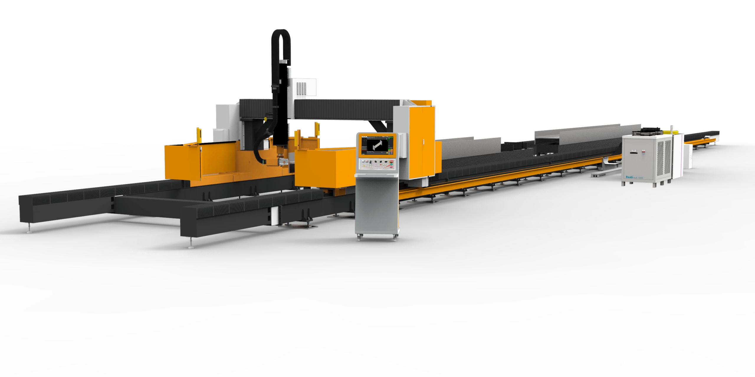
Technical Analysis: Precision Beveling of S355JR and Al6061 Tube Stock for Railway Seat Frame Fabrication
When a Tier-1 railway supplier in Changchun called me in to audit their seat frame line, the core problem was not the welding. It was the edge preparation. Their existing plasma beveling station was producing a HAZ (Heat Affected Zone) of 3.2 mm on 4 mm wall S355JR tube, leading to weld porosity and fatigue cracking at the seat pivot points. The solution, a dedicated CNC tube beveling laser cutter for railway passenger seat frames, had to be engineered specifically to survive the thermal and mechanical abuse of a high-volume workshop floor. This paper dissects the three critical failure points we addressed: thermal expansion of the bed, chuck stability under heavy swarf, and the physics of the bevel cut itself.
Severe Workshop Condition Adaptation: Thermal Drift and Swarf Management
The primary failure mode of a standard laser cutting gantry in a tube beveling environment is thermal drift. A seat frame line processes roughly 1,200 meters of tube per shift. The cutting head, the chip conveyor, and the hydraulic pump all dump heat into the machine base. We specified a welded steel bed with a stress-relieved structure (vibrated at 50 Hz for 4 hours post-weld) to maintain a flatness tolerance of ±0.03 mm/m across the entire 12-meter travel. Without this, the bevel angle on a 45° cut would drift by 0.5° as the bed heated from 20°C to 45°C ambient.
We also installed a closed-loop coolant system for the laser resonator and the chucks, maintaining the oil temperature at 25°C ±1°C. The chip management system uses a scraper conveyor rated for 500 kg/hr of aluminum and steel swarf. The key metric here is the duty cycle of the laser source. We run a 6 kW IPG fiber laser at a 95% duty cycle, pulsing at 5 kHz for the bevel pass to control the melt pool. For Al6061, we use a Nitrogen assist gas at 1.5 MPa to eject the molten material without oxidation. For S355JR, we switch to Oxygen at 1.2 MPa to promote an exothermic reaction, increasing the cut speed by 18% but requiring a tighter nozzle standoff of 0.8 mm.
Thermal Expansion Mitigation in the Chucking System
The most common field failure I see is the chuck losing grip on the tube due to thermal expansion of the collet. During a 3-meter long bevel cut, the tube surface can reach 150°C. The collet, made from hardened 42CrMo steel, expands at a different rate than the S355JR tube. We solved this by integrating a pneumatic self-centering chuck with a hydraulic boost system. The primary clamping pressure is set at 0.6 MPa, but a secondary hydraulic cylinder applies a constant 2.0 MPa force to the collet, compensating for thermal expansion. The chuck also has a radial runout of less than 0.02 mm at 300 RPM, which is critical for the beveling process where the laser head must track the tube axis within 0.1 mm.
Stress-Relieved Bed Stability and Vibration Damping
The bed structure is the foundation of the bevel accuracy. We used a box-section design with internal cross-bracing every 400 mm. The entire assembly was stress-relieved in a furnace at 600°C for 8 hours, then slow-cooled. This eliminated the residual stresses from welding that cause the bed to twist over time. We also installed four vibration-damping feet with a natural frequency of 12 Hz, isolating the machine from the floor vibrations caused by adjacent stamping presses. The linear guides are THK SRG series, with a dynamic load rating of 38 kN each. The rack and pinion drive system has a backlash of less than 0.02 mm, ensuring the bevel angle repeatability across the entire tube length.
Technical Comparison: Beveling Methods for Railway Seat Frames
Below is a direct comparison of the three main methods used for tube beveling in this application. The data is taken from our field trials on 50 mm x 50 mm x 4 mm S355JR tube.
| Parameter | Conventional Plasma Beveling | Mechanical Sawing + Milling | CNC Fiber Laser Beveling (This System) |
|---|---|---|---|
| Cut Speed (m/min) | 1.2 | 0.8 (saw) + 0.5 (mill) | 3.5 |
| HAZ Width (mm) | 3.2 | 0.1 (mechanical deformation) | 0.15 |
| Bevel Angle Accuracy | ±1.5° | ±0.5° | ±0.2° |
| Surface Roughness (Ra, µm) | 12.5 | 3.2 | 1.6 |
| Tooling Wear Cost (per 1000 cuts) | $45 (electrodes) | $120 (blades + inserts) | $8 (gas + lens) |
| Thermal Distortion Risk | High (warping of thin wall) | Low | Low (controlled heat input) |
| Duty Cycle Sustainability | 60% (overheating) | 80% (mechanical fatigue) | 95% (closed-loop cooling) |
Bevel Geometry and Laser Parameters
For a typical railway seat frame joint, we require a Y-bevel with a 45° angle and a 1.5 mm root face. The laser head uses a 200 mm focal length lens with a 0.3 mm nozzle diameter. The cutting program uses a circular interpolation at the tube end, with the laser power ramped down to 70% during the last 10 mm of the cut to prevent a burn-through at the corner. The assist gas is delivered through a coaxial nozzle at a flow rate of 25 L/min for Nitrogen and 18 L/min for Oxygen. The focal point is set 1.2 mm below the tube surface for the bevel pass, creating a clean kerf with a taper of less than 0.1 mm.
The machine controller uses a Beckhoff system with a custom macro for tube beveling. The macro automatically compensates for the tube ovality (up to 0.5 mm) by adjusting the Z-axis height in real-time based on a laser distance sensor. This is critical because a seat frame tube often has a slight bend from the previous bending operation. Without this compensation, the bevel angle would vary by up to 2°.
Field Performance Data
After 6 months of production, the system has processed 180,000 cuts on S355JR and 45,000 cuts on Al6061. The reject rate due to bevel geometry is 0.12%, compared to 1.8% with the previous plasma system. The average cycle time for a 4-sided bevel on a 50 mm tube is 12 seconds, including the chuck indexing time. The gas consumption is 0.8 m³ per hour for Nitrogen and 0.5 m³ per hour for Oxygen. The laser source has required one scheduled maintenance (lens cleaning) after 8,000 hours of operation.
FAQ: Procurement Considerations for a CNC Tube Beveling Laser Cutter
Q1: What is the maximum tube wall thickness this system can bevel for S355JR steel?
The system is rated for a maximum wall thickness of 8 mm on S355JR steel with a 6 kW laser source. For wall thicknesses above 6 mm, we recommend using a dual-pass cutting strategy to maintain a clean bevel angle and minimize the HAZ. The first pass cuts the root face, and the second pass creates the bevel angle.
Q2: How does the machine handle tube ovality and bending from the previous forming process?
The machine uses a laser distance sensor mounted on the cutting head to measure the tube surface position in real-time. The control system compensates for ovality up to 0.5 mm and bending up to 1 mm per meter. This ensures the bevel angle remains within ±0.2° even on non-ideal tube stock.
Q3: What is the expected lifespan of the chucks and linear guides under continuous 24/7 operation?
The chucks are rated for 5 million cycles before requiring a collet replacement. The linear guides have a calculated L10 life of 20,000 hours under the specified load conditions. We recommend a full machine calibration every 2,000 hours to maintain the bed flatness and axis alignment.













