Metallurgical and Kinematic Demands of Telescopic Mast Rail Fabrication
The production of forklift telescopic masts is not a generic tube-cutting operation. It is a high-stakes exercise in managing long, slender profiles—typically S355JR or S460ML hot-rolled steel—where the length-to-diameter ratio often exceeds 40:1. When you are cutting 8-meter sections of 120x80x6mm rectangular hollow sections (RHS) for the inner and outer boom stages, the tolerance stack-up is unforgiving. A deviation of ±0.5mm in the weld prep bevel at the base end translates directly into a misaligned carriage weld and premature wear on the mast rollers. The specific challenge here is not just cutting speed; it is the CNC automatic pipe cutter for forklift telescopic mast production system’s ability to maintain absolute dimensional stability over a full shift while dealing with thermal drift and the mechanical shock of chip evacuation.
Severe Workshop Condition Adaptation: The Real Enemy is the Environment
Let us be blunt about the workshop floor. It is not a cleanroom. The ambient temperature swings by 10-15°C between the morning start-up and the afternoon peak load. The machine bed is subjected to falling scale, coolant mist, and the vibration from adjacent plate rolling machines. In this environment, a conventional rack-and-pinion drive with a cast iron bed will betray you. The coefficient of thermal expansion for cast iron is roughly 10.4 x 10⁻⁶ /°C. On a 12-meter bed, a 15°C shift induces a linear growth of nearly 1.9mm. That is catastrophic for a mast section requiring a 0.1mm positional repeatability.
To counter this, the modern solution employs a stress-relieved welded steel bed structure, specifically fabricated from low-carbon structural steel plates. The critical step is the post-weld heat treatment (PWHT) cycle—typically holding the bed at 600°C for 4 hours, followed by a controlled furnace cooling at 20°C/hour down to 200°C. This reduces residual stresses to below 20% of the yield strength. But the thermal expansion issue remains. The engineering answer is not to fight the expansion but to measure and compensate for it. The machine must integrate a glass scale feedback system on the Y-axis (longitudinal feed) that reads the actual position relative to the bed, not the motor encoder. This closed-loop feedback, with a resolution of 0.001mm, effectively negates the thermal growth of the ball screw or rack, ensuring the cut length accuracy of ±0.15mm is maintained regardless of the ambient temperature.
Thermal Expansion Mitigation at the Cutting Zone
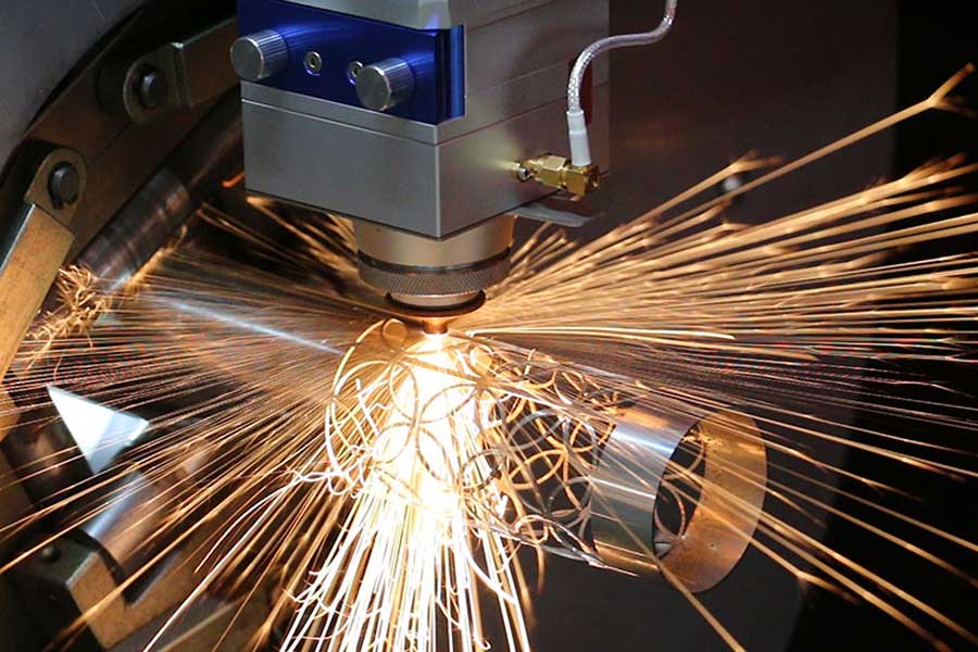
The laser cutting process itself is a concentrated heat source. When cutting 6mm wall thickness S355JR, the focal point generates a kerf width of roughly 0.3mm. The immediate heat-affected zone (HAZ) on the cut edge will reach temperatures exceeding 1000°C. If the clamping mechanism holds the tube rigidly at both ends without allowance for axial expansion, the tube will buckle. The solution lies in the intelligent chuck design. The front chuck (near the cutting head) must provide absolute clamping force—typically 80-120 kN via hydraulic actuation at 15 MPa. However, the rear support chuck must operate in a “sliding” mode, maintaining radial centering with a lower pressure (around 5 MPa) to allow the tube to expand longitudinally away from the cut zone. This prevents the “pinching” effect that causes the tube to bow and the cut to become elliptical.
Furthermore, the assist gas delivery is critical for thermal management. For clean, dross-free cuts on galvanized or primed mast sections, we utilize nitrogen at a delivery pressure of 1.2 to 1.5 MPa. This high-pressure nitrogen not only expels the molten metal but also acts as a cooling medium, reducing the heat soak into the main body of the tube. If oxygen is used for faster cutting of thicker walls (10-12mm), the pressure drops to 0.5-0.8 MPa, but the exothermic reaction increases the heat input. In this case, the CNC program must automatically reduce the feed rate by 15% during the last 20mm of the profile cut to allow the material to cool and prevent the final corner from “blowing out.”
Stress-Relieved Bed Stability and Drive Mechanics
The drive system on a mast-specific cutter must handle the inertia of a heavy tube. A 12-meter, 6mm wall RHS weighs approximately 1800 kg. To accelerate this mass to 20 m/min without inducing vibration, the servo motor must deliver a peak torque of 45 Nm, coupled with a low-backlash planetary gearbox (ratio 10:1). The rack and pinion drive, with a module of 2.5, must be preloaded against the rack to eliminate backlash—typically using a dual-pinion anti-backlash system. The pinion springs must exert a constant force of 3000N to maintain mesh contact even during rapid deceleration.
The bed stability is further enhanced by the use of polymer concrete (mineral casting) in the machine base, not just steel. While steel is strong, it has low damping capacity. Polymer concrete, with a damping factor 6-8 times higher than steel, absorbs the high-frequency vibrations generated by the laser’s high-speed cutting head movements (often exceeding 1g acceleration). This damping is crucial when cutting complex profiles like the “C” channel or the “J” hook shapes on the mast rail ends, where the cutting head must change direction rapidly. Without this damping, the micro-vibrations would cause a “chatter” mark on the cut surface, which becomes a stress riser under the cyclic loading of the fork mast.
Let us compare the operational reality of the laser solution against the legacy methods:
| Parameter | Conventional Sawing / Plasma | CNC Fiber Laser Solution |
|---|---|---|
| Cutting Tolerance (Length) | ±2.0 mm (mechanical stop variation) | ±0.15 mm (closed-loop glass scale) |
| Kerf Width | 3-5 mm (saw blade) / 4-6 mm (plasma) | 0.2 – 0.4 mm (fiber laser, 3kW-6kW source) |
| Heat Affected Zone (HAZ) | 1.5 mm (plasma) – 2.0 mm (saw burr) | < 0.1 mm (minimal thermal distortion) |
| Material Utilization | 85% (due to kerf loss and scrap ends) | 95%+ (nested cutting, minimal kerf) |
| Secondary Operations | Deburring, slag removal, grinding required | None required; edge is ready for welding |
| Cycle Time (per 8m tube, 6 holes + 2 end cuts) | 4 minutes (multi-station handling) | 1 minute 45 seconds (single pass, automatic) |
| Operator Intervention | High (manual measurement, tool wear checks) | Low (automatic tool compensation, remote monitoring) |
Process Gas and Frequency Parameters for Mast Steel
For the specific application of cutting S355JR (yield strength 355 MPa), the fiber laser source is typically operated at a wavelength of 1064 nm. The cutting parameters are not static. For a 4mm wall, we run at 3kW power, 80 Hz pulse frequency, and a 20% duty cycle. This pulsing creates a “percussive” effect that helps eject the viscous molten slag. For a 6mm wall, the power increases to 4kW, but the frequency drops to 50 Hz to allow the laser to penetrate deeper before the assist gas blows the material through. The focal position is critical—it must be set at -2mm below the top surface for optimal energy coupling. If the focal point is too high, the bottom edge will have a heavy burr; if too low, the top edge will be rounded.
Regarding the chuck pneumatic system, the clamping pressure is not constant. The system must read the tube’s actual dimensions via a laser profile scanner before clamping. If the tube is slightly out-of-square (a common issue with hot-rolled sections), the chuck pressure must be adjusted dynamically to avoid crushing the corners. The standard clamping pressure for a 6mm wall RHS is 8 MPa, but if the scanner detects a deviation of 0.5mm in the width, the pressure is reduced to 6 MPa to prevent indentation, while the axial grip is maintained by increasing the friction coefficient with a serrated jaw insert.
The integration of the cutting process with the upstream drilling and downstream tapping operations is where the true efficiency lies. The CNC controller must handle the “C” axis (tube rotation) and the “Y” axis (longitudinal feed) simultaneously. When cutting a complex saddle cut for the mast cross-member, the tube rotates at 30 RPM while the head moves linearly at 1.5 m/min. The synchronization error between these axes must be less than 0.02mm to ensure the bevel angle is consistent. This is achieved via a high-speed EtherCAT bus with a cycle time of 1ms, ensuring that the servo drives receive position updates without lag.
Finally, the chip and fume management system is not an afterthought. The laser cutting of steel with nitrogen produces a fine metallic dust that is highly conductive. If this dust settles on the linear guides, it will quickly destroy the bearing surfaces. The machine must be equipped with a high-vacuum extraction system (minimum 5000 m³/h) integrated directly into the cutting head, and the guideways must be protected by telescopic steel covers with positive air pressure. The filter system must be a multi-stage cartridge type, with a pre-separator for large particles and a HEPA final filter for the sub-micron particles, ensuring the workshop air quality remains within OSHA compliance limits.
Frequently Asked Questions for Procurement Engineers
Q1: How does the machine handle the thermal expansion of the long steel tubes during a continuous production run, specifically regarding the chuck clamping force?
The system uses a dual-zone clamping strategy. The front chuck maintains a rigid grip (high pressure) to establish the datum point. The rear chuck operates in a floating mode with reduced pressure, allowing the tube to slide axially as it expands due to ambient temperature changes. The CNC software monitors the tube length via the glass scale and automatically adjusts the rear chuck position to compensate for any growth, preventing buckling and ensuring the cut length remains within tolerance.
Q2: What is the specific cycle time and maintenance interval for cutting a 6mm thick S355JR mast section with multiple holes and end profiles?
For a standard 8-meter mast section with 8 holes (20mm diameter) and two profiled end cuts, the total cycle time is approximately 1 minute 45 seconds. The laser source (6kW) requires scheduled maintenance every 20,000 hours of operation, primarily involving the replacement of the protective cover glass on the cutting head, which is a 5-minute procedure. The focus lens cleaning interval is every 4 hours of continuous operation, depending on the assist gas purity.
Q3: Can this system integrate with our existing MES/ERP system for production tracking and quality traceability?
Yes. The CNC controller is equipped with an OPC-UA interface that allows seamless data exchange with your MES system. It transmits real-time data on cut lengths, cycle times, gas consumption, and alarm states. Furthermore, the system logs the exact process parameters (laser power, gas pressure, feed rate) for each cut part, creating a digital twin record that enables full traceability from raw material batch to finished mast section, which is essential for ISO 9001 and forklift safety certifications.













