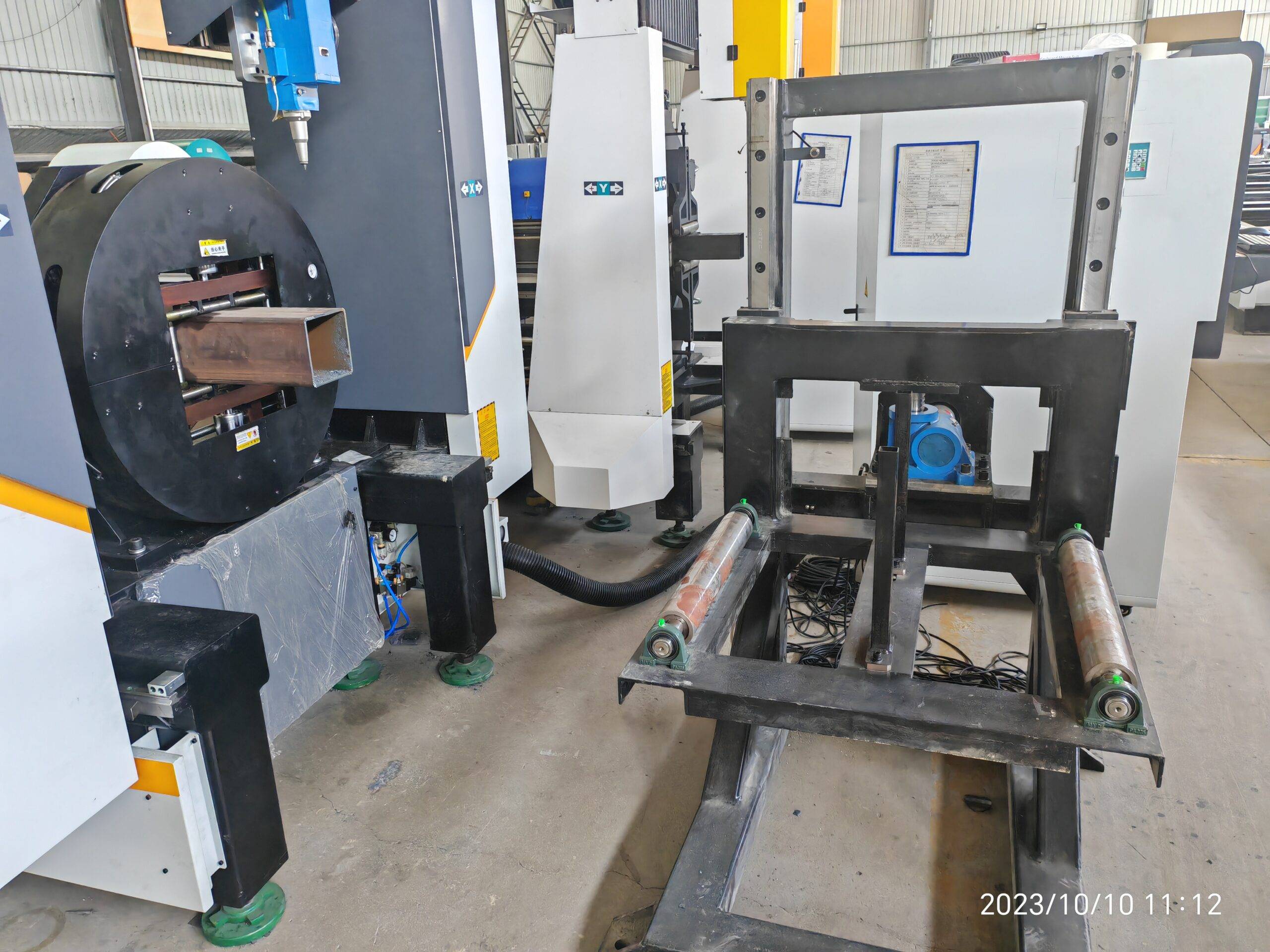
Operational Realities of High-Volume Upright Tube Processing: A Field Service Perspective
When a racking manufacturer moves from batch-mode fabrication to a synchronized production cell, the bottleneck almost never sits at the laser source itself. It sits at the interface between material handling, tube geometry, and the maintenance discipline applied to the cutting head. The automated warehouse racking system upright tube laser cutter is a specific class of machine that must hold ±0.15 mm positional accuracy on 6-meter uprights with punched slots, weld-prep bevels, and mitered ends — all while running 18 to 22 hours per day. That duty cycle exposes every weak point in the consumable chain.
This paper addresses three interconnected realities that determine whether such a cell achieves 85% OEE or collapses to 55% within nine months: after-sales troubleshooting diagnostics, consumables lifecycle management, and preventive maintenance scheduling calibrated to actual thermal and mechanical load.
Material-Specific Cutting Parameters and Their Maintenance Consequences
Racking uprights are predominantly produced from S355JR (EN 10025-2) structural steel, with yield strength of 355 MPa and a carbon equivalent typically between 0.38 and 0.45. Some premium racking lines use SUS304 for cold-storage or food-grade installations, and a smaller segment uses Al6061-T6 for lightweight mezzanine uprights. Each material imposes distinct wear profiles on the laser system.
For S355JR at 3.0 mm wall thickness, a 4 kW fiber source with nitrogen assist at 1.4 MPa and a 1.6 mm nozzle orifice produces clean edges at 4.2 m/min. The oxygen route for thicker sections (5.0 to 8.0 mm) runs at 0.6 to 0.9 MPa with a focus shift of +1.5 mm. The critical maintenance consequence: oxygen cutting generates dross adhesion on the nozzle tip and accelerates lens contamination by a factor of 2.5 compared to nitrogen cutting. A shop running 70% oxygen cuts will replace protective windows every 180 to 220 hours, not the 500 hours quoted in the sales brochure.
SUS304 requires nitrogen at 1.5 MPa minimum and higher peak power to overcome reflectivity. The 1070 nm wavelength reflects approximately 38% on polished stainless, which means back-reflection protection diodes on the cutting head are under constant thermal stress. These diodes are a consumable, not a permanent component. Field data shows a mean time between failure of 4,000 to 5,500 operating hours on 4 kW heads running stainless daily.
Comparative Analysis: Legacy Methods vs. Integrated Laser Cell
| Parameter | Plasma Cutting + Manual Drilling | Mechanical Sawing + Punch Press | Fiber Laser Tube Cell (Integrated) |
|---|---|---|---|
| Dimensional tolerance on slot position | ±1.2 mm | ±0.5 mm | ±0.15 mm |
| Edge quality (Ra) | 25–40 µm, heavy dross | 12–18 µm, burr on exit | 3.2–6.3 µm, dross-free with N₂ |
| Consumable cost per 1,000 uprights | $180 (electrodes, tips, drill bits) | $420 (saw blades, punch tooling) | $95 (nozzles, windows, diodes amortized) |
| Changeover time (profile A to B) | 45–70 min | 90–120 min | 4–8 min (chuck auto-centering) |
| Heat-affected zone | 1.5–3.0 mm | None (mechanical) | 0.05–0.15 mm |
| Post-process operations required | Grinding, deburring, reaming | Deburring, chamfering | None for most slot geometries |
Chuck and Clamping System: The Hidden Failure Point
Upright tubes are rarely perfectly straight. Mill tolerance on S355JR square tube allows 0.15% deviation over length, which on a 6-meter upright means up to 9 mm of bow. A pneumatic chuck clamping at 0.6 MPa on a bowed tube induces eccentric rotation. At 80 RPM, that eccentricity translates to radial runout at the cutting head of 0.4 to 0.7 mm. The autofocus system compensates, but the servo axis on the Z-slide absorbs the oscillation, and the linear guide bearings degrade prematurely.
Field troubleshooting protocol: measure runout at three points along the tube — 200 mm from chuck, mid-span, and 200 mm from the steady rest. If variance exceeds 0.3 mm, the issue is upstream in material storage, not the machine. This is where preventive maintenance intersects with incoming inspection. A racking manufacturer storing upright stock on unlevel cantilever racks will introduce bow that no laser compensation can fully correct.
Consumables Lifecycle Management: Data-Driven Replacement
Nozzle life on a tube laser running S355JR at 4 kW averages 120 to 160 hours for single-layer chrome-plated copper nozzles with a 1.6 mm orifice. The failure mode is not orifice wear — it is spatter adhesion that changes the gas flow dynamics. A nozzle with 0.1 mm of accumulated dross on the tip face shifts the kerf width by 0.08 mm and increases dross on the bottom edge.
- Protective window: replace at 15% power transmission loss, measured with a handheld power meter. Typical interval: 200 hours (O₂ cutting), 450 hours (N₂ cutting).
- Ceramic nozzle holder: inspect for micro-cracks every 500 hours. Thermal cycling at 4 kW with 60% duty cycle induces stress fractures at the thread root.
- Chuck jaws: measure clamping force with a load cell every 1,000 hours. Below 80% of rated force, replace. Worn jaws on a 6-meter tube allow slippage during rapid positioning, causing position errors of 0.5 to 1.0 mm.
- Focus lens: inspect under magnification every 250 hours. Contamination on the lens surface causes localized heating and focal shift. A lens with 0.05 mm focal shift produces 0.2 mm kerf taper on 5 mm S355JR.
Preventive Maintenance Scheduling Aligned to Duty Cycle
A machine running 20 hours per day, 6 days per week accumulates 6,240 operating hours annually. The manufacturer’s recommended 2,000-hour service interval is inadequate for this duty cycle. Field experience dictates a tiered schedule:
Daily: nozzle inspection, gas pressure verification at the regulator (not the machine gauge), chuck jaw wipe-down, and runout check on the first tube of each shift. Weekly: protective window inspection, X/Y axis lubrication, and chiller coolant level and conductivity check (target 5 to 10 µS/cm). Monthly: focus lens inspection, chuck clamping force measurement, and ball screw backlash check on the Z-axis. Quarterly: laser source power calibration, gas delivery system leak test at 1.5 MPa, and full optical path alignment.
The most common after-sales call on these machines is not a laser failure. It is a gas delivery problem — moisture ingress in the nitrogen line causing inconsistent assist pressure, which manifests as intermittent dross and poor edge quality. A dew point monitor on the gas line, checked weekly, prevents 60% of these calls.
What is the typical nozzle life when cutting S355JR with oxygen assist on a tube laser?
Expect 120 to 160 hours for a 1.6 mm single-layer chrome-plated copper nozzle at 4 kW. Oxygen cutting generates more spatter than nitrogen, and spatter adhesion on the nozzle tip face is the primary failure mode — not orifice wear. Replace when kerf width shifts by more than 0.08 mm or when bottom-edge dross becomes consistent.
How often should chuck clamping force be verified on an automated upright tube laser?
Every 1,000 operating hours using a calibrated load cell. Below 80% of rated clamping force, the jaws must be replaced. Worn jaws allow tube slippage during rapid positioning, producing cumulative position errors of 0.5 to 1.0 mm over a 6-meter upright, which fails racking tolerance requirements.
What causes intermittent dross on stainless steel uprights cut with nitrogen?
Moisture ingress in the nitrogen delivery line. Even at 1.5 MPa, trace moisture causes inconsistent assist gas pressure at the kerf, producing intermittent dross and rough edges. Install a dew point monitor at the point of use and verify weekly. This single check prevents roughly 60% of after-sales quality complaints on stainless tube cutting.













