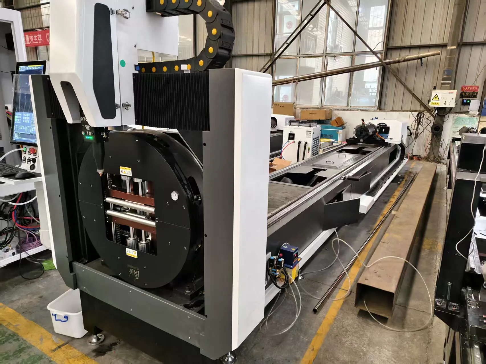
When we talk about tolerances of tube laser cutting in aerospace and automotive brackets, we are not discussing cosmetic edge quality. We are discussing the difference between a bracket that survives 10^7 load cycles and one that fails at the bolt hole due to micro-cracks induced by thermal stress. In my experience running production lines for Tier 1 suppliers, the shift from mechanical sawing and plasma to fiber laser tube processing isn’t just a speed upgrade; it is a fundamental change in how we manage residual stress and dimensional stability. For aerospace (typically Al6061-T6 or Ti-6Al-4V) and automotive (S355JR or DP800), the acceptance criteria often sit at ±0.1 mm on hole-to-hole positioning and ±0.05 mm on profile flatness. Achieving this consistently requires a deep dive into the physics of the cut, not just the CNC code.
Advanced Nesting Software Algorithms and Material Yield Maximization
The first battleground is not the laser head; it is the nesting algorithm. In high-mix, high-volume bracket production, the difference between 78% and 92% material utilization is the difference between winning and losing the contract. Standard nesting software treats the tube as a static 2D surface. That is a mistake. We are cutting 3D profiles where the kerf width (typically 0.2 mm to 0.3 mm on a 6 kW laser) and the taper angle (usually 0.5° to 1.5° depending on focus position) must be compensated for in the algorithm.
We utilize advanced nesting algorithms that perform dynamic collision avoidance and thermal load balancing. The software does not just pack parts; it sequences them to prevent heat accumulation in a localized zone of the tube. If we cut a dense cluster of small brackets on a 60 mm diameter S355JR tube, the residual heat can cause the tube to bow by up to 0.5 mm over a 3-meter length. The algorithm must interleave cuts—cut one part on the top, then one on the bottom, then rotate the chuck—to allow the material to dissipate heat. This is where the “common-line cutting strategy” becomes critical.
Common-line Cutting Strategy and Thermal Distortion Control
Common-line cutting, or shared-edge cutting, is not just about saving material. It is about managing the stress release. When cutting two adjacent brackets from a single tube, if we cut them as separate entities, we create two separate heat-affected zones (HAZ). The residual stress from the first cut can distort the material before the second cut begins. By using a common-line strategy, we cut the shared edge once, effectively halving the HAZ and reducing the thermal input by roughly 30% on that specific joint. This is crucial for maintaining the ±0.1 mm tolerance on the mounting holes that align with the vehicle chassis.
In practice, we run a 4 kW to 6 kW IPG fiber laser with a cutting head equipped with a 150 mm focal length lens. For aluminum brackets (Al6061), we operate at a frequency of 5 kHz with a duty cycle of 100% (CW) but reduce the power to 3.2 kW to avoid melting the back wall of the tube. The assist gas is Nitrogen at 1.4 MPa delivery pressure. If we drop below 1.2 MPa, we see dross adherence on the bottom edge, which immediately throws the profile tolerance out of spec. For steel (S355JR), we switch to Oxygen at 1.5 MPa, but we must reduce the cutting speed by 15% to allow the exothermic reaction to complete without leaving a nitride layer that hardens the edge and causes cracking during bending.
Comparative Analysis: Conventional vs. Fiber Laser Processing
To quantify the operational shift, let us look at the raw data from a recent line audit for a suspension bracket (material: S355JR, tube OD 48.3 mm, wall thickness 4.0 mm).
| Parameter | Mechanical Sawing + Drilling | Plasma Cutting | Fiber Laser Tube Cutting (6 kW) |
|---|---|---|---|
| Positional Tolerance (Hole-to-Hole) | ±0.5 mm (tool wear dependent) | ±0.3 mm (kerf erosion) | ±0.05 mm (consistent) |
| Profile Edge Squareness | N/A (mechanical burr) | 5° – 8° taper | 0.5° – 1° taper |
| Heat Affected Zone (HAZ) Depth | 0.0 mm (cold cutting) | 0.8 mm – 1.2 mm | 0.1 mm – 0.2 mm |
| Cycle Time per Bracket (4 holes + 2 notches) | 2 min 45 sec | 1 min 30 sec | 38 sec |
| Material Yield (per 6m tube) | 82% (saw kerf loss 3mm) | 85% (wide kerf) | 94% (narrow kerf + common-line) |
| Secondary Operations Required | Deburring, chamfering | Grinding, straightening | None (if gas pressure is correct) |
Notice the cycle time. The laser achieves this speed because it performs the cutting and the hole drilling in the same pass, utilizing a piercing routine that ramps the power from 10% to 100% in 50 milliseconds to avoid reflective backscatter damage on the optics. The chuck pneumatic pressure is set to 0.6 MPa for this OD. If we increase the pressure to 0.8 MPa, we risk crushing the tube wall on thin-wall sections (2.0 mm), causing a 0.2 mm ovality that ruins the bracket fit-up.
The key to maintaining these tolerances over a full production shift is the focus control. We use an automatic focus adjustment that compensates for the thermal lensing effect in the cutting head. After 30 minutes of continuous cutting, the optics heat up, shifting the focal point by up to 0.4 mm. If uncorrected, this shifts the kerf width and increases the taper angle. The CNC controller must actively adjust the Z-axis by -0.01 mm per minute to compensate. This is not a “set and forget” operation; it requires the operator to monitor the capacitive height sensor feedback in real-time.
Furthermore, the nesting software must account for the “last piece” scenario. When cutting a 6-meter tube, the final 300 mm is often unusable due to chuck clamping marks. The algorithm must automatically shift the nest to ensure that the most tolerance-critical bracket (usually the one with the 12.0 mm H7 hole for the steering column) is placed in the middle of the tube, away from the high-stress zones at the ends where the chuck jaws (pressure 0.6 MPa) create micro-deformations.
FAQ: Industrial B2B Procurement
Q1: What is the minimum wall thickness we can process on a tube laser without losing the ±0.1 mm tolerance for automotive brackets?
For automotive structural brackets, we routinely process S355JR and DP800 with wall thicknesses down to 1.5 mm. However, below 2.0 mm, you must switch to a higher frequency (10 kHz) and lower pulse width to reduce the heat input. At 1.5 mm wall, we run at 2 kW power, Nitrogen at 1.2 MPa, and a cutting speed of 8 m/min. If you go below 1.5 mm, you will see significant warping unless you use a specialized low-frequency pulse (500 Hz) to create a “cold cut” effect, but this reduces speed by 40%.
Q2: How does the common-line cutting strategy affect the structural integrity of the bracket edges?
Common-line cutting does not compromise integrity if the assist gas pressure is maintained. The shared edge has a slightly higher surface roughness (Ra 3.2 µm vs. Ra 1.6 µm on a single cut) due to the double pass of the laser beam on the same line. For aerospace brackets where fatigue life is critical, we recommend specifying a secondary deburring pass with a 0.2 mm radial offset to clean the edge. For automotive, the Ra 3.2 µm is acceptable for non-visible mounting brackets.
Q3: Can we retrofit our existing plasma cutting CNC to handle fiber laser tube cutting tolerances?
No. The dynamics are entirely different. Plasma requires a standoff distance of 3-5 mm, while fiber laser requires 0.5-1.0 mm. The acceleration profiles are also different; a laser needs 2g acceleration to maintain the tight corners on a bracket profile, while plasma typically runs at 0.5g. You would need to replace the gantry, the drive motors, and the control software. It is more cost-effective to invest in a dedicated tube laser system with a 3D nesting package that supports common-line cutting.













