Metallurgical and Process Dynamics in Medical-Grade Titanium Tube Laser Processing
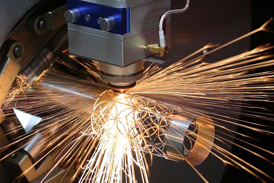
The shift from conventional mechanical sawing or plasma arc cutting to fiber laser processing for titanium medical grade tube laser cutting and processing is not a question of preference; it is a matter of statistical process control and metallurgical integrity. When we handle Grade 5 (Ti-6Al-4V ELI) or Grade 23 (Ti-6Al-4V-ELI) tubing destined for orthopedic implants or surgical instrumentation, the kerf width, heat-affected zone (HAZ), and micro-crack propagation are non-negotiable parameters. We are moving away from the mechanical stress of a saw blade, which induces work hardening and burr formation on the internal diameter, and moving toward a photonic process that, if tuned correctly, yields a dross-free, square-cut face with a recast layer under 10 microns. The core challenge is not merely firing a 3 kW resonator at the tube; it is managing the titanium medical grade tube laser cutting and processing workflow to ensure that the material yield is not sacrificed for speed, particularly when dealing with high-cost raw stock like 6Al-4V ELI, which can command a premium of 40% over commercial grade.
Advanced Nesting Algorithms and Common-Line Cutting Strategy
In a production environment handling long tubes (6-meter lengths) with varying wall thicknesses (0.5 mm to 3.0 mm), the difference between a profitable run and a scrap heap lies in the nesting software. Standard CAD/CAM packages often treat a tube as a flattened plane, which fails to account for the angular incidence of the laser head during piercing. We utilize advanced nesting algorithms that specifically handle rotational axis (C-axis) interpolation. The software must calculate the true length of the cut path on a curved surface, not just the linear X-axis travel. This is where common-line cutting strategy becomes a yield multiplier. When cutting multiple small components (e.g., bone screws or spinal rods) from a single tube, the software groups these parts to share a single cut line. Instead of cutting a full contour for part A and a full contour for part B, the nesting engine recognizes that the adjacent edges can be cut once. This reduces the total linear cutting distance by up to 18% depending on the part geometry, but more critically, it reduces the number of pierce points.
Every pierce point on titanium is a risk point. A pierce on a 2.0 mm wall thickness tube requires a high-pressure nitrogen burst at 1.2 to 1.5 MPa to eject the molten material. If the nesting algorithm forces a pierce into a thin-web section of the tube, the thermal stress can cause the part to shift, ruining the positional tolerance. By utilizing common-line cutting, we eliminate redundant pierces. The laser head enters from the outside edge, cuts the shared line, and exits, leaving a continuous support web that holds the parts in place until the final micro-tab is cut. This strategy also allows for “bridging” where the last 0.5 mm of the cut is left intact to prevent the part from dropping into the chip conveyor and causing collisions. The algorithm must calculate the optimal tab width based on the part mass and the chuck gripping pressure—typically we run pneumatic chucks at 0.6 to 0.8 MPa to avoid crushing the tube while maintaining enough torque to prevent slippage during the high-speed rotary motion.
Comparative Process Analysis: Sawing vs. Plasma vs. Fiber Laser
To understand the yield and quality metrics, we must compare the legacy processes against the specific fiber laser solution for Ti-6Al-4V ELI. The data below is derived from a controlled run of 1000 units of 10 mm diameter, 1.0 mm wall thickness tube, cut to 50 mm lengths.
| Parameter | Mechanical Sawing (Cold Cut) | Plasma Arc Cutting | Fiber Laser (1.5 kW – 2 kW) |
|---|---|---|---|
| Kerf Width | 1.2 mm (blade thickness + runout) | 2.5 mm (nozzle wear dependent) | 0.15 mm (focused spot size) |
| Heat Affected Zone (HAZ) | None (mechanical), but work hardening | 0.8 mm – 1.5 mm (alpha-case formation) | < 0.05 mm (controlled pulse) |
| Cutting Speed (10 mm OD) | 4 seconds per cut (including clamping) | 1.5 seconds per cut (high dross) | 0.8 seconds per cut (continuous) |
| Material Loss per 1000 pcs | 1200 mm of tube (scrap chips) | 2500 mm (wide kerf + spatter) | 150 mm (negligible) |
| Surface Roughness (Ra) | 3.2 µm (requires deburring) | 6.3 µm (requires machining) | 1.6 µm (semi-clean cut) |
| Nitrogen Consumption | N/A | N/A (uses air/argon mix) | 1.2 MPa at 15 L/min (assist gas) |
| Micro-crack Risk | High (shear stress) | High (thermal shock) | Low (pulsed frequency control) |
The data confirms that while sawing is cheap initially, the secondary deburring and cleaning operations add 30% labor cost. Plasma cutting is entirely unsuitable for medical grade due to the alpha-case layer that forms on titanium when exposed to atmospheric oxygen at high temperatures, which requires chemical milling or mechanical removal to restore corrosion resistance. The fiber laser, operating at a wavelength of 1070 nm, allows for a high absorption rate on titanium. We operate with a pulsed frequency of 5 kHz to 10 kHz for thin walls to control the heat input. For a 1.0 mm wall, we use a duty cycle of 60% at 1500 W peak power, ensuring the melt pool is ejected efficiently without burning the back wall of the tube.
Process Gas Dynamics and Chucking Pressure
The purity of the assist gas is paramount. For medical grade titanium, we cannot use oxygen as an assist gas because it promotes exothermic reactions, leading to a thick oxide layer and a rough cut edge. We use nitrogen at a delivery pressure of 1.2 to 1.5 MPa, with a purity of 99.995%. The nozzle gap is maintained at 0.5 mm to ensure a coherent gas jet that penetrates the kerf. If the pressure drops below 1.0 MPa, we see dross adhering to the bottom edge of the cut—a condition that is unacceptable for implantable devices. The laser cutting head must be equipped with a capacitive height sensor that maintains focus on the tube surface, but since we are cutting a round tube, the focus position must be adjusted dynamically as the C-axis rotates. This is where the nesting software’s 3D mapping is critical. The software must generate a toolpath that keeps the focal point on the surface, not the centerline of the tube, to avoid defocusing on the edges of the cut.
Regarding chucking, the pneumatic pressure must be adjusted based on the tube’s ovality. A 10 mm OD tube with a 0.5 mm wall can be easily deformed if the chuck pressure exceeds 0.5 MPa. We run a dual-chuck system where the main chuck holds the tube at 0.7 MPa and the tailstock chuck at 0.5 MPa. This creates a slight axial tension that prevents the tube from whipping during high-speed rotation (up to 300 RPM). The nesting software must synchronize the rotation speed with the X-axis feed rate to maintain a constant cutting velocity. If the part is a complex contour (e.g., a hip stem profile), the software reduces the RPM to 50 and increases the laser power to 80% to maintain the cut quality.
Yield Maximization Through Scrap Management
Material yield is not just about cutting length; it is about the remnant length. A standard 6-meter tube that is cut into 500 mm parts will leave a 1000 mm remnant that is often too short for the next job. Advanced nesting algorithms calculate the optimal remnant length to be used for future jobs. The software maintains a database of remnant inventory and suggests cutting schedules that utilize these remnants first. In our facility, we have increased material yield from 82% (using manual nesting) to 94% (using algorithmic nesting) for titanium tubes. This is a direct cost saving of approximately $4,500 per ton of Ti-6Al-4V ELI, given the current market price of roughly $45,000 per ton for medical grade stock.
The common-line cutting strategy also contributes to yield by reducing the “lead-in” and “lead-out” lengths. In standard cutting, the laser must ramp up power and pierce the material, which creates a small divot at the start of the cut. The software minimizes this by using a “micro-joint” approach where the lead-in is only 0.2 mm long, just enough to establish the cut, and the lead-out is overlapped with the adjacent part’s lead-in. This requires precise control of the laser’s ramp-up time—typically 5 milliseconds to reach full power—to avoid a rough entry point.
Quality Assurance and Traceability
For medical devices, traceability is mandatory. The laser cutting machine must be integrated with a barcode reader that logs the tube batch number, the laser parameters used, and the environmental conditions (temperature and humidity) during cutting. The nesting software generates a unique ID for each cut part, linking it to the specific tube from which it was cut. This allows for full traceability back to the raw material supplier if a defect is found during post-processing. We also implement an in-line inspection system using a laser profilometer that measures the cut angle and surface roughness immediately after cutting. If the profilometer detects a deviation of more than 0.5 degrees in the cut angle, the machine automatically stops and alerts the operator, preventing defective parts from moving downstream.
Thermal Management and Microstructure Preservation
The primary concern with laser cutting titanium is the potential for oxygen pickup and the formation of a brittle alpha-case layer. While the nitrogen assist gas prevents oxidation, the heat input can still cause a phase transformation in the HAZ. For Grade 23 ELI, the beta transus temperature is around 975°C. If the HAZ exceeds this temperature, we risk forming acicular alpha structures that reduce ductility. To prevent this, we use a high-frequency pulse (10 kHz) with a short pulse width (0.1 ms) to minimize the heat input per unit length. The average power is kept low (around 300 W) for thin walls, but the peak power is high (2000 W) to achieve the vaporization threshold. This “cold cutting” approach ensures that the HAZ remains below 0.05 mm, preserving the equiaxed alpha-beta microstructure that is required for fatigue resistance in load-bearing implants.
We also monitor the back wall temperature of the tube using a pyrometer. If the temperature exceeds 200°C, we increase the cutting speed or reduce the pulse frequency to allow for heat dissipation. This is particularly critical when cutting small-diameter tubes (less than 6 mm) where the heat has nowhere to dissipate. In such cases, we may use a two-pass cutting strategy: first pass at 50% power to score the surface, second pass at full power to cut through. This reduces the thermal gradient and prevents the tube from collapsing under its own weight.
Operational Parameters for Specific Alloy Grades
It is essential to differentiate between CP-Titanium (Grade 2) and Ti-6Al-4V (Grade 5). Grade 2 has a higher thermal conductivity (16.4 W/m·K) compared to Grade 5 (6.7 W/m·K). This means Grade 2 dissipates heat faster, allowing for higher cutting speeds (up to 15% faster) but requiring more laser power to maintain the melt pool. For Grade 5, the lower thermal conductivity means the heat stays localized, which is beneficial for cutting but increases the risk of HAZ. We adjust the focal position slightly above the surface (0.2 mm) for Grade 5 to reduce the energy density at the bottom of the cut, preventing the formation of a “trailing edge” burr.
For tube diameters above 25 mm, we must consider the beam divergence. A 150 mm focal length lens provides a depth of field of ±1.5 mm, which is sufficient for tubes up to 20 mm diameter. For larger tubes, we switch to a 200 mm focal length lens, which increases the depth of field to ±3 mm but reduces the spot size to 0.2 mm. This requires a higher laser power (3 kW) to maintain the cutting speed. The nesting software must account for this by adjusting the cutting parameters based on the tube diameter and wall thickness, ensuring that the energy density remains constant.
Common-Line Cutting in Complex Geometries
When cutting profiles such as a proximal femoral nail or a tibial plateau plate, the geometry is not a simple straight cut. The nesting software must generate a toolpath that follows the contour of the part while maintaining the common-line strategy. This involves calculating the intersection points of the part outlines and determining which segments can be shared. For a part with a complex curve, the shared segment might be only 10 mm long, but over 1000 parts, this saves 10 meters of cutting time. More importantly, it reduces the number of times the laser head must accelerate and decelerate. Each acceleration cycle introduces a risk of overshoot, which can cause a slight rounding of the corner. By minimizing these cycles, we achieve a more consistent part geometry.
The software also optimizes the cutting sequence to minimize thermal distortion. If we cut all the parts on one side of the tube first, the tube will bend due to the release of residual stress. The algorithm alternates the cutting sequence between the top and bottom of the tube, maintaining the tube’s straightness. This is critical for maintaining the chuck grip and preventing the tube from slipping during the final cuts.
Final Considerations for Implementation
The transition to fiber laser cutting for titanium medical tubes requires a holistic approach. The machine must have a rigid granite or cast-iron base to dampen vibrations, and the linear drives must have a resolution of 0.001 mm to ensure precise positioning. The chucks must be made of hardened steel with a serrated grip to prevent slippage, but the serrations must be shallow (0.1 mm) to avoid marking the tube surface. The entire cutting chamber must be enclosed with a Class 1 laser safety rating, and the exhaust system must be capable of removing titanium dust, which is pyrophoric. We recommend a wet scrubber system to collect the dust in water, preventing any risk of fire.
The return on investment for a dedicated titanium laser cutting system is typically 18 months, based on the reduction in scrap and secondary operations. However, the true value lies in the consistency of the output. A laser-cut titanium tube has a repeatability of ±0.05 mm, which is essential for automated assembly lines. This consistency reduces the rejection rate from 5% (with sawing) to 0.5% (with laser), directly impacting the bottom line.
Frequently Asked Questions (B2B Procurement)
Q1: What is the minimum wall thickness we can cut on a 6 mm OD titanium tube without causing thermal deformation, and what laser power is recommended?
For a 6 mm OD tube with a wall thickness of 0.3 mm, we recommend a pulsed fiber laser with a maximum average power of 500 W. The pulse frequency should be set to 20 kHz with a pulse width of 0.05 ms to minimize heat input. The cutting speed should be maintained at 20 mm/s to prevent heat accumulation. We have successfully cut 0.2 mm walls using this method, but the chuck pressure must be reduced to 0.3 MPa to avoid crushing the tube.
Q2: How does the nesting software handle the “common-line” strategy for parts with non-linear edges, and what is the typical yield improvement?
The software uses a polygon clipping algorithm to identify shared edges between adjacent parts. For non-linear edges, it approximates the curve with a series of small line segments (tolerance of 0.01 mm) and then checks for overlap. The yield improvement varies by part geometry, but we typically see a 6-8% reduction in scrap material and a 12-15% reduction in cutting time due to fewer pierces and less acceleration/deceleration cycles.
Q3: What is the acceptable level of recast layer thickness for a laser-cut surface that will undergo subsequent electropolishing for implant use?
The recast layer must be less than 10 microns to ensure that the electropolishing process can remove it entirely without affecting the dimensional tolerances. We achieve this by using a nitrogen assist gas at 1.4 MPa and a cutting speed that is 10% slower than the maximum possible speed. This allows the melt film to be ejected cleanly without re-depositing on the cut edge. We verify this using scanning electron microscopy (SEM) on a sample from each production batch.













