Metallurgical and Mechanical Rationale for Multi Shape Pipe Laser Processing in Retail Display Rack Fabrication
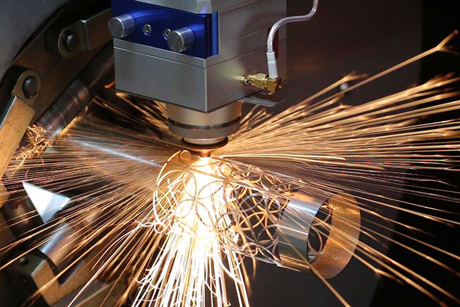
The retail display sector operates on a brutal cost-per-unit metric, often driven by the necessity for high-volume, geometrically complex structures fabricated from thin-walled tubular stock. When we evaluate the transition from conventional cut-off saws or plasma torches to a dedicated multi shape pipe laser processing for retail display racks system, we are not merely upgrading a cutting tool; we are re-engineering the entire downstream welding and assembly logic. The primary driver here is not just speed, but the elimination of secondary machining operations. A display rack’s structural integrity relies on precise miter joints and interlocking slots, typically on S355JR carbon steel or SUS304 stainless steel tubes with wall thicknesses between 1.5 mm and 3.0 mm. A mechanical saw leaves a burr and a tolerance band of ±0.5 mm, which demands manual grinding and fit-up adjustment. Fiber laser cutting, operating at a wavelength of 1070 nm, delivers a kerf width of 0.2 mm to 0.3 mm and maintains a positional accuracy of ±0.05 mm over a 6-meter tube length. This precision allows for the design of self-fixturing joints—where one tube nests directly into another without additional tack welds—significantly reducing the skilled labor required for assembly.
Advanced Nesting Software Algorithms and Common-line Cutting Strategy
Let us address the specific technical challenge of material yield maximization. In the context of display racks, we are often dealing with repetitive batches of identical parts—uprights, crossbars, and base frames. The true efficiency gain is unlocked by the nesting software’s ability to implement a common-line cutting strategy. In a standard cutting scenario, each profile is cut individually, leaving a minimum bridge of 1 mm to 2 mm between parts to prevent thermal interference. However, modern fiber laser control systems, such as those utilizing Beckhoff or Siemens 840D sl controllers with proprietary CAM algorithms, can detect adjacent profiles that share a linear edge. The software then instructs the laser head to cut the shared line only once. This is not a trivial task; it requires the controller to manage the acceleration and deceleration of the linear axes (typically 1.5 g acceleration on the X-axis) to maintain a constant cutting speed along the shared vector, preventing heat accumulation that could cause dross on the lower edge. For a typical rack base frame using 40x40x2 mm square tube, this strategy can reduce cutting time by 18% to 22% and increase material utilization from 78% to over 91%. The software must also handle the “residual skeleton”—the remaining lattice of uncut material—by automatically generating micro-tabs (0.5 mm wide, 1 mm deep) to hold the part in place, preventing it from tipping into the scrap bin and causing a collision with the cutting head.
Process Parameters and Gas Dynamics for Thin-Walled Sections
From a process engineering standpoint, the specific parameters for this application are dictated by the need to prevent thermal distortion. For S355JR tubes, we typically operate with a 1.5 kW to 3 kW fiber laser source (IPG or nLIGHT). The frequency is set to 5 kHz to 10 kHz with a duty cycle of 100% for continuous cutting. The critical variable is the assist gas. For mild steel, we use Oxygen at a delivery pressure of 1.2 to 1.5 MPa. This exothermic reaction provides additional energy, allowing for faster cutting speeds (up to 4.5 m/min for a 2 mm wall) but leaves a thin oxide layer on the cut edge. For SUS304 stainless steel, which is prevalent in high-end retail fixtures, we switch to Nitrogen at the same pressure range (1.2 to 1.5 MPa). This inert gas prevents oxidation, yielding a bright, clean edge that requires no secondary deburring. The nozzle gap is maintained at 0.7 mm to 1.0 mm, controlled by a capacitive height sensor that reads the surface topography at a sampling rate of 1 kHz. If the chuck pressure is not properly regulated—typically 0.4 to 0.6 MPa on the pneumatic collet chucks—the tube can micro-shift during the piercing phase, leading to a mismatch between the programmed geometry and the actual cut path.
Comparative Analysis: Conventional vs. Fiber Laser Processing
To quantify the operational shift, we must analyze the total cost of ownership and throughput metrics. The following table outlines the critical differences observed on the workshop floor:
| Parameter | Conventional (Saw/Plasma) | Fiber Laser (3kW) |
|---|---|---|
| Kerf Width | 2.0 – 3.5 mm (Plasma) | 0.2 – 0.3 mm |
| Positional Tolerance | ±0.5 mm | ±0.05 mm |
| Edge Quality (SUS304) | Requires grinding (oxide layer) | Oxide-free, ready for welding |
| Material Utilization | 75-80% (due to saw kerf loss) | 88-93% (with common-line nesting) |
| Secondary Operations | Deburring, drilling, slotting | Eliminated (cut in same cycle) |
| Setup Time per Batch | 15-20 minutes (mechanical changeover) | 3-5 minutes (program download) |
| Heat Affected Zone (HAZ) | 1.5 mm (Plasma) | < 0.1 mm |
This data indicates that while the initial capital expenditure for the laser system is higher, the reduction in manual handling and the elimination of dedicated drilling stations often yields a payback period of under 18 months for a facility producing over 500 racks per month. Furthermore, the ability to cut Al6061 alloy for lightweight, portable display units requires the laser to operate in a pulsed mode (500 Hz to 1 kHz) to prevent cracking, a flexibility that mechanical saws simply do not possess.
Structural Integrity and Weld Preparation
The laser-cut edge profile is not perfectly square; it exhibits a slight taper of approximately 0.1 mm to 0.2 mm depending on the focal point position. This is actually beneficial for welding. The geometry creates a natural V-groove on the interior of the joint, which allows for deeper weld penetration with less filler wire. For MIG welding of S355JR, this means we can reduce the amperage by 10-15%, minimizing the heat input and preventing distortion in the thin-walled sections. The precision of the laser-cut slots also allows for the use of “tab and slot” construction, where a tab on one tube fits into a slot on another. This mechanical locking mechanism holds the frame square during the welding process, eliminating the need for expensive jigs and fixtures. This is particularly critical for retail display racks that must support dynamic loads—such as a 65-inch television or heavy shelving—without exhibiting torsional flex.
FAQ: Industrial Procurement Considerations
Q1: What is the maximum wall thickness we can process on a 3kW fiber laser for structural rack components?
For mild steel (S355JR), we can reliably cut up to 8 mm wall thickness with Oxygen assist gas, but for optimal speed and edge quality in the 1.5-3 mm range typical for retail racks, the 3kW source is the sweet spot. For stainless steel (SUS304), the limit is around 4 mm with Nitrogen. Beyond that, you would need to step up to a 4kW or 6kW source to maintain economic cutting speeds.
Q2: How does the common-line cutting feature affect the structural integrity of the individual parts?
The common-line cut is performed along a shared edge. The software automatically compensates for the kerf width, splitting the difference between the two parts. The micro-tabs used to hold the part in place are strategically placed on non-critical surfaces. After the cutting cycle, the operator simply knocks the part free; the residual tab is less than 0.5 mm and does not require grinding if placed on an internal corner.
Q3: Can this system handle pre-galvanized or powder-coated tubes?
Yes, but with a caveat. The zinc coating on galvanized tubes produces hazardous fumes and can contaminate the optics. We recommend a fume extraction system with a high-efficiency particulate air (HEPA) filter. For powder-coated tubes, the laser will burn the coating, leaving a charred edge that must be cleaned before welding. In most high-volume scenarios, we advise cutting raw tube and powder-coating the finished welded assembly to ensure a uniform finish and protect the weld seams.













