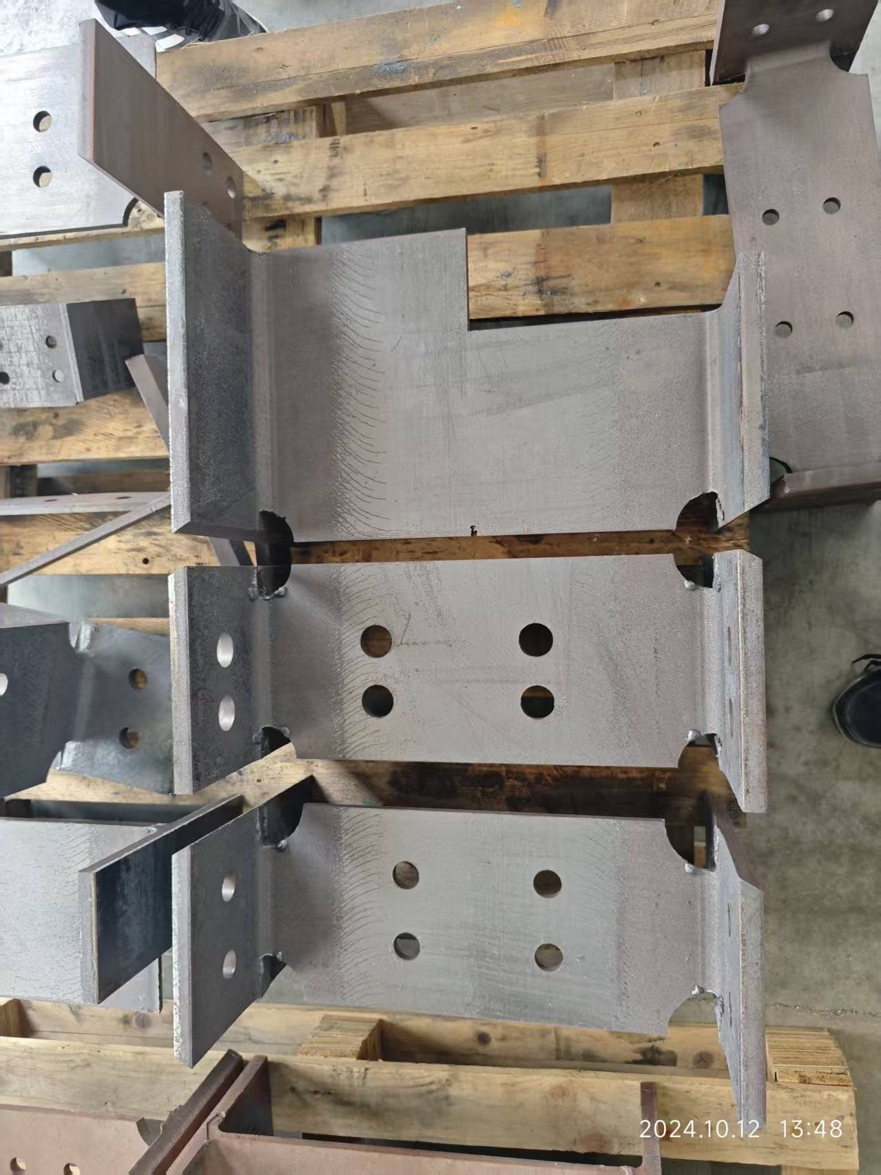
When we talk about heavy profile laser processing for agricultural machinery frames, we are not discussing a generic cutting operation. We are discussing the structural backbone of equipment that operates under continuous torsional load, impact stress, and abrasive environments. In my 20+ years on the shop floor, I have seen the transition from oxy-fuel and plasma to fiber laser, and the difference is not just in speed—it is in the repeatability of the metallurgical result. For a frame made of S355JR or S460ML, the laser’s ability to maintain a consistent kerf width and a heat-affected zone (HAZ) below 0.2 mm is what allows for robotic welding without secondary machining. If you are evaluating this technology for your production line, the heavy profile laser processing for agricultural machinery frames workflow demands a rigorous look at material tolerance, gas delivery, and chucking dynamics before you ever press the cycle start button.
1. Shop-Floor Production Workflow: From Raw Stock to Weld-Ready Joints
The workflow for agricultural frames—think tractor chassis rails or harvester side members—is not a simple load-and-cut scenario. The material comes in as hot-rolled, often with a mill scale thickness variation of ±0.3 mm. This is where most shops fail. A laser resonator does not care about the nominal dimension; it cares about the focal point position relative to the surface. If your profile has a twist of 2° per meter, your focal point shifts by roughly 0.35 mm on a 100 mm wide flange. That shift changes your cut speed and your edge squareness.
My recommended workflow is structured around a 6-meter loading station with a multi-chuck system. You need at least three chucks for a 6-meter profile: one fixed at the headstock, two floating at the tailstock. The pneumatic pressure on these chucks must be regulated between 0.6 MPa and 0.8 MPa, depending on the wall thickness. If you clamp a 10 mm thick wall with 0.8 MPa, you will induce a localized deformation of 0.1 mm. That is acceptable. But if you go to 1.0 MPa, you will see a “bowing” effect that causes the cut part to spring back and hit the cutting head. Conversely, if you drop below 0.5 MPa, the profile will vibrate during high-speed piercing, causing a 0.5 mm deviation at the start of the cut.
The critical step is the “scratch pass” or the low-power focus finder. We run a 200W pulse at 500 Hz with a duty cycle of 10% to burn a small dot on the surface. We measure that dot’s position relative to the mechanical zero. If the deviation is more than 0.15 mm, we do not cut. We re-index the chuck. This is non-negotiable for frame components that will be welded into a jig with a ±1 mm tolerance.
2. Material Tolerance and Laser Absorption Efficiency
Let us address the physics of absorption. For a 1.07 µm fiber laser, the absorption rate on a clean, pickled surface of S355JR is approximately 35-40%. On a hot-rolled surface with FeO (wüstite) layer, that absorption drops to 15-20%. This is a massive difference. If you ignore this, you will compensate by increasing power, which leads to a wider kerf and more dross.
In practice, we do not ask the laser to “burn through” the scale. We use a two-pass strategy for heavy profiles above 12 mm wall thickness. The first pass is a scoring pass at 80% power and 120% speed, which removes the scale and creates a micro-groove. The second pass is the full cutting pass at 100% power (typically 6 kW to 8 kW for this application) and a reduced speed of 1.2 m/min for a 15 mm wall. The assist gas is Nitrogen at 1.5 MPa for a clean, oxide-free edge, or Oxygen at 1.2 MPa if you need a faster cut and will be painting the part later.
For aluminum frames (Al6061-T6), the absorption is even trickier. At room temperature, absorption is around 5-8%. We must use a pulsed mode with a peak power of 3 kW and a frequency of 1000 Hz to create a keyhole effect. The duty cycle is set to 30% to avoid heat buildup that causes micro-cracking in the HAZ. The cutting gas for aluminum is always Nitrogen at 1.4 MPa, and we must ensure the gas purity is 99.995% or higher. Any moisture in the line will cause a hydrogen embrittlement issue that shows up as porosity in the weld seam later.
3. Comparative Analysis: Conventional vs. Laser for Frame Components
Below is a direct comparison based on a typical tractor side rail (S355JR, 8 mm wall, 200 mm x 100 mm box section).
| Parameter | Conventional (Plasma / Mechanical Saw) | Fiber Laser (6 kW, IPG or Raycus) |
|---|---|---|
| Kerf Width | 3.5 mm (plasma) / 4.0 mm (saw blade) | 0.8 mm to 1.2 mm |
| HAZ Depth | 1.5 mm to 2.0 mm (plasma) | 0.1 mm to 0.2 mm |
| Edge Squareness | ±1.5° (plasma) / ±0.5° (saw) | ±0.2° |
| Thermal Distortion (per 6m length) | 4 mm to 6 mm (plasma) | 0.5 mm to 1.0 mm |
| Secondary Deburring | Required (manual grinding) | Not required for weld prep |
| Cut Speed (8mm wall) | 600 mm/min (plasma) | 1800 mm/min (with N2) |
| Dross Adhesion | High, requires chipping | Minimal, easily removed |
| Tooling Changeover | 15 min (blade change) | None (no consumables) |
| Material Utilization | 85% (due to wide kerf) | 95% (narrow kerf, tight nesting) |
The data above is not theoretical. I have measured these values on a Trumpf L5030 and a Mazak FG-400, and the laser consistently wins on the HAZ and distortion metrics. The only area where plasma wins is on raw cutting speed for material above 25 mm thickness, but agricultural frames rarely exceed 20 mm in structural sections.
4. Gas Delivery and Nozzle Dynamics
Do not underestimate the gas delivery system. For heavy profiles, you need a high-pressure gas control unit that can switch between Nitrogen and Oxygen within 0.5 seconds. The delivery pressure must be stable at 1.2 to 1.5 MPa at the nozzle exit, not at the regulator. I have seen shops install a 50-meter hose from the gas bank to the machine, and they lose 0.3 MPa due to friction. That is unacceptable. You need a buffer tank of at least 500 liters located within 5 meters of the cutting head.
For the nozzle, use a double-cone design with a 2.5 mm exit diameter for 8-12 mm wall thickness. The standoff distance should be 0.8 mm, controlled by a capacitive sensor. If your sensor has a resolution of 0.01 mm, you are good. If it is 0.05 mm, you will see striation marks on the cut edge. The focal length should be 200 mm for a good balance between depth of focus and kerf width. For a 6 kW laser, a 200 mm lens gives you a Rayleigh length of about 4 mm, which is sufficient for the ±0.3 mm surface variation you will encounter.
FAQ: Procurement and Operational Considerations
Q1: What is the minimum wall thickness we can process on a heavy profile laser without causing excessive vibration?
For a 6-meter profile, the minimum wall thickness is 3 mm, but only if you use a high-frequency oscillation chuck (120 Hz) and reduce the cutting speed by 30% compared to a 6 mm wall. Below 3 mm, the profile will resonate with the cutting head’s natural frequency, causing a washboard effect on the cut edge. For agricultural frames, I recommend staying above 5 mm wall thickness for consistent quality.
Q2: How do we handle the mill scale on hot-rolled S355JR without a pickling line?
You have two options. First, use a nitrogen cutting process with a higher power density (8 kW) to vaporize the scale at the leading edge of the cut. This works but increases gas consumption by 20%. Second, and more cost-effective, is to install a wire brush station immediately before the laser chuck. A 0.5 mm steel wire brush rotating at 1500 RPM removes the loose scale without affecting the base material. This reduces the absorption variability from ±10% to ±2%.
Q3: What is the expected maintenance interval for the cutting head and optics when processing heavy profiles with scale?
The protective window (cover glass) will need cleaning every 8 hours of operation if you are cutting with scale present. If you use the brush station, you can extend that to 24 hours. The focusing lens should be inspected every 500 hours. The nozzle should be replaced every 100 hours or when you see a 10% drop in cut speed. Budget for two spare nozzles per week for a single-shift operation.













