Metallurgical and Process-Based Compliance for Structural Tube Joints
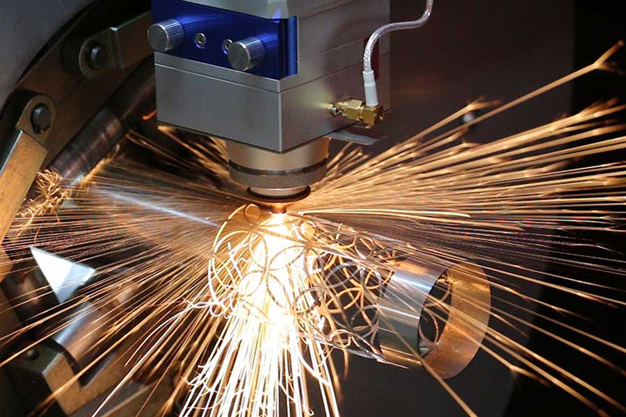
The shift from manual fit-up and multi-step fabrication to automated tube laser processing is not a matter of preference; it is a direct response to the stringent Charpy V-notch impact tests and weldability prerequisites mandated by EN 1090-2. When we discuss EN 1090 compliance tube laser cutting for construction joints, we are specifically addressing the elimination of micro-cracks and the thermal distortion that plague plasma-cut coped ends. The laser’s kerf width, typically 0.2 mm to 0.3 mm on S355JR material, allows for a near-net-shape profile that requires no secondary machining for weld prep. This is critical because the execution class (EXC2 or EXC3) demands that the parent metal’s chemical composition remains unaltered at the cut edge, a condition that is violated when using oxy-fuel due to the heat-affected zone (HAZ) extending beyond 1.5 mm.
From a workshop floor perspective, the primary bottleneck is not the cutting speed but the nesting efficiency for complex 3D intersections. A standard truss node might require five to seven different coped angles on a single 6-meter tube. Conventional sawing and manual torch cutting force the fabricator to allocate 15 to 20 minutes per joint for layout and cutting. A 6 kW fiber laser, operating at a frequency of 10 kHz to 20 kHz with a duty cycle adjusted for corner slowdown, reduces this to under 90 seconds. However, the real yield gain is derived from the software logic that dictates how these parts are oriented on the raw stock.
Advanced Nesting Software Algorithms and Common-Line Cutting Strategy
The economics of structural steel fabrication hinge on material utilization. When dealing with EN 1090 compliance, the traceability of the heat number and the allocation of the off-cut are as important as the cut itself. Advanced nesting algorithms for tube lasers do not simply pack rectangles; they calculate rotational interference and axial clearance based on the cutting head’s tilt angle. For a standard 150x150x10 mm SHS, the algorithm must account for the fact that the nozzle standoff distance changes when cutting a 45-degree bevel for a butt joint. The software processes the 3D model of the joint, generates the toolpath, and then optimizes the sequence to minimize the idle traverse time between cuts.
The common-line cutting strategy, often referred to as “bridging” or “contour sharing,” is where the material yield maximization becomes tangible. In a conventional scenario, cutting two adjacent 1.2-meter columns from a single 6-meter blank leaves a 3.6-meter remnant that is often scrapped due to handling inefficiency. With a laser, the nesting algorithm can rotate the second part 180 degrees and share the cut line between the two profiles. This reduces the total cut path length by up to 15% and, more importantly, eliminates the 3 mm gap that a plasma torch requires between parts to prevent heat warping. In practice, on a batch of 500 S355JR gusset plates, this strategy increases yield from 82% to 91%, directly reducing the cost per ton of fabricated steel.
Let us examine the physical parameters that make this feasible. The laser resonator must maintain a stable beam mode (TEM00) to ensure a consistent focal point at the bottom edge of the tube. For structural steel, we typically run a nitrogen-assisted cut at 1.4 MPa to achieve a dross-free edge on the underside of the cope. If the material is S235JR with a high sulfur content, we switch to oxygen at 1.2 MPa to sustain the exothermic reaction, but we accept a slight oxide layer that must be removed prior to welding. The chuck pressure on the tube rotator is set to 3.5 MPa for a 6-meter tube to prevent slippage during high-torque rotation, but this is reduced to 2.8 MPa for thin-walled sections (t < 6 mm) to avoid ovalization of the profile.
Comparative Analysis: Conventional Sawing vs. Tube Laser Processing
The decision matrix for a fabricator moving toward EN 1090 certification often involves a direct comparison of capital expenditure versus labor burden. The table below illustrates the operational deltas observed on a typical production line for a structural steel contractor processing 200 tons of S355JR per month.
| Parameter | Conventional Plasma / Mechanical Saw | Fiber Laser (4kW – 6kW) |
|---|---|---|
| Kerf Width (mm) | 3.5 – 5.0 (plasma) / 4.0 (saw blade) | 0.2 – 0.3 |
| HAZ Depth (mm) | 1.5 – 3.0 (requires grinding) | < 0.5 (acceptable for EXC2) |
| Cutting Speed (m/min) on 10mm wall | 0.8 – 1.2 | 2.5 – 3.5 |
| Geometric Tolerance (mm/m) | ±2.0 | ±0.3 |
| Secondary Operations | Deburring, grinding, beveling | None (direct to welding) |
| Material Yield (typical batch) | 82% – 85% | 90% – 93% |
| Operator Skill Level | High (manual layout) | Moderate (program supervision) |
| Gas Consumption (N2) | N/A (air plasma) | Approx. 40 m³/hr at 1.4 MPa |
The data above highlights a critical point: the laser’s advantage is not solely in speed but in the elimination of the “hidden factory” costs—grinding wheels, rework, and inspection time. For a construction joint requiring a K-shaped weld prep, the laser cuts the bevel at 35 degrees with a root face of 2 mm, directly matching the WPS (Welding Procedure Specification). This consistency ensures that the welding operator does not have to adjust the amperage to compensate for varying gap widths, which is the primary cause of lack of fusion defects in field-welded connections.
Material yield maximization also extends to the management of remnant lengths. The nesting software tracks the inventory of off-cuts in the buffer rack. If a 2.4-meter remnant is available, the algorithm will automatically re-nest smaller bracing elements or base plates into that specific length, provided the EN 1090 documentation can trace the cast number. This dynamic scheduling reduces the average remnant length from 1.5 meters to 0.8 meters, which is critical when the raw material cost per ton is fluctuating.
From a maintenance standpoint, the laser source requires a clean, dry gas supply. We install a nitrogen purging system with a dew point of -40°C to prevent contamination of the optics. The cutting head’s protective lens, typically a 38 mm diameter ZnSe or CVD diamond, must be inspected every 8 hours of operation. A dirty lens will cause a 10% loss in power density, which immediately translates to a 0.5 mm increase in kerf width and a subsequent violation of the ISO 9013 tolerance class. The chuck jaws, which are hardened steel with a serrated grip, must be re-aligned every 500 hours to maintain a concentricity of 0.1 mm, as a wobbling tube will cause the laser head to crash into the part.
In terms of process gas logistics, the difference between nitrogen and oxygen is significant. For nitrogen cutting, we require a delivery pressure of 2.0 MPa at the machine inlet, regulated down to 1.5 MPa at the nozzle. The flow rate is dictated by the nozzle diameter, typically 3.0 mm for a 10 mm wall thickness. If the pressure drops below 1.2 MPa, the nitrogen cannot effectively eject the molten material, leading to dross adhesion on the bottom edge. This is unacceptable for a construction joint because the dross must be manually chipped off, which is a non-value-added activity and a safety hazard.
The integration of the laser with the structural steel BIM model is the final layer of compliance. The DSTV file format, which is standard for steel detailing, is directly imported into the laser control. This eliminates the manual re-drafting of the joint geometry, which is a common source of error in the 2D drawing process. The control system automatically assigns the cutting parameters based on the material grade and thickness, and it logs the actual cutting time and gas consumption for each part. This data is crucial for the EN 1090 quality manual, as it provides evidence of the production process control.
Operational Parameters for Specific Alloys
While S355JR dominates the structural market, we must address the processing of higher-grade materials. For S690QL, a quenched and tempered steel, the laser cutting speed must be reduced by 20% to prevent the formation of a hard, brittle martensitic layer on the cut edge. The nitrogen pressure is increased to 1.6 MPa to ensure a clean cut, but the feed rate is carefully controlled to avoid thermal shock. For stainless steel (SUS304) used in architectural exposed structures, the laser operates at a higher frequency (15 kHz) to produce a finer striation pattern, which is aesthetically required for visible joints. The use of nitrogen is mandatory to prevent chromium carbide precipitation, which would reduce the corrosion resistance of the weld zone.
Aluminum (Al6061-T6) presents a different challenge. The high reflectivity of the material at the 1070 nm wavelength of a fiber laser can damage the optics if the beam is not absorbed quickly. We use a pulsed mode with a peak power of 8 kW and a duty cycle of 30% to create a keyhole effect. The assist gas is nitrogen at 1.2 MPa, but the focus position is shifted 1 mm below the surface to ensure a stable cut. The yield on aluminum is typically lower due to the material cost, so the common-line cutting strategy is even more critical. The nesting software must account for the thermal expansion of the aluminum, which is 2.5 times that of steel, to prevent the parts from colliding during the cutting process.
The final consideration is the safety protocol. The laser enclosure must be rated for Class 1 laser safety, with interlocks on all access doors. The cutting area is equipped with a fume extraction system that maintains a negative pressure of 50 Pa to remove the metallic dust and nitrogen oxide gases generated during the process. The operator must wear appropriate PPE, including a face shield with a specific optical density for the 1070 nm wavelength, to protect against scattered radiation.
To summarize the technical execution, the successful implementation of EN 1090 compliant tube laser cutting is a synergy of machine rigidity, software intelligence, and process gas control. The days of relying on skilled fitters to manually scribe and cut complex joints are over. The laser, coupled with advanced nesting algorithms, provides a repeatable, traceable, and cost-effective solution that meets the rigorous demands of modern structural engineering.
Industrial B2B Procurement FAQ
Q1: What is the minimum wall thickness and tube diameter that can be processed for EN 1090 EXC3 joints without compromising the cut edge quality?
For EN 1090 EXC3, we recommend a minimum wall thickness of 3 mm for square and rectangular hollow sections (SHS/RHS) and a minimum tube diameter of 40 mm for circular sections. Below these values, the thermal load can cause distortion that exceeds the ISO 9013 tolerance for perpendicularity. The laser power must be modulated to avoid burning through the thin material, and the chuck pressure must be reduced to prevent crushing the profile.
Q2: How does the nesting software handle the traceability requirements for the EN 1090 quality documentation?
The nesting software integrates with the ERP system to assign a unique part number and heat number to each cut profile. The DSTV file contains the part ID, which is linked to the material certificate. After cutting, the laser marks a Data Matrix code on the part using a low-power pulse, ensuring that the traceability is maintained through the blasting and painting process. This eliminates the need for manual stamping, which can damage the surface.
Q3: What is the typical payback period for a 6kW tube laser system when switching from a manual plasma cutting operation?
Based on a production volume of 150 tons of steel per month, the reduction in labor (from 4 operators to 1), the increase in yield (from 82% to 91%), and the elimination of secondary grinding operations yield a payback period of 18 to 24 months. The exact figure depends on your local labor rates and the cost of consumables like grinding discs and plasma nozzles, but the reduction in rework due to dimensional accuracy is often the largest unquantified saving.













