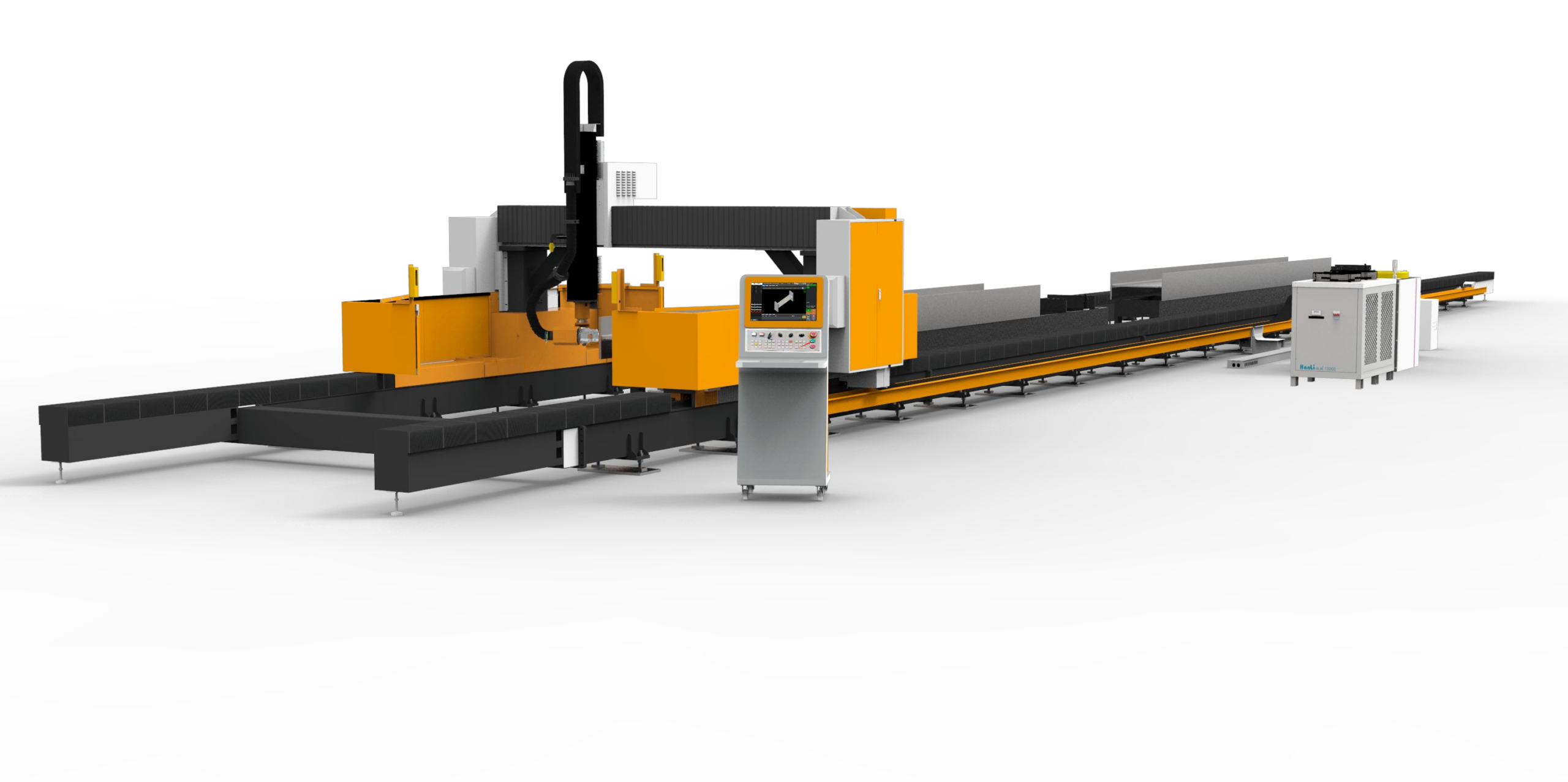
EN 1090 Compliance Tube Laser Cutting for Construction Joints: A Field Perspective on Nesting Algorithms, Common-Line Strategy, and Yield Maximization
Walking a fabrication floor that handles S355JR or S355J2H structural hollow sections, the difference between a profitable job and a loss leader often comes down to how you manage the kerf, the pierce points, and the remnant. When you are cutting nodes for trusses or gusset plates for moment connections, the tolerance stack-up is unforgiving. You cannot afford the thermal distortion you get from plasma or the mechanical deformation from a cold saw. That is why shifting to EN 1090 compliance tube laser cutting for construction joints is not just a quality upgrade; it is a fundamental change in how you allocate raw material and machine hours. Let’s get into the physics and the programming logic that makes this work on the shop floor.
The Physics of the Cut: Why Laser Beats Sawing and Plasma for Joint Prep
For a construction joint—whether a K-joint, Y-joint, or an overlap joint—you need a bevel angle that allows for full penetration welds without excessive filler metal. A band saw gives you a straight cut, forcing you to manually cope or profile the tube end. Plasma gives you a cut but leaves a dross layer and a heat-affected zone (HAZ) that can reach 3-4 mm deep on a 10 mm wall, which compromises the mechanical properties of the S355 grade. A fiber laser, running at a wavelength of 1064 nm, cuts with a focused spot size of 0.2 to 0.3 mm. This allows for a kerf width of only 0.3 to 0.5 mm, compared to 3-5 mm for plasma. The specific energy input is drastically lower, so the HAZ is typically under 0.5 mm. This is critical for maintaining the yield strength at the joint interface.
When we talk about beveling, a 5-axis laser head is non-negotiable. You are not just tilting the head; you are maintaining a constant focal point position relative to the cut front. For a 10 mm wall thickness in S355J2H, we typically run a 6 kW to 8 kW resonator. The assist gas is Nitrogen for a clean, oxide-free edge when you need to paint or galvanize later. Delivery pressure is set at 1.2 to 1.5 MPa to blow the molten material out of the kerf without creating a burr on the underside. If you are cutting thicker sections (over 15 mm) and you are going to weld immediately without surface treatment, you might switch to Oxygen at 0.5 to 0.8 MPa to get a slightly faster cut speed, accepting a thin oxide layer that is actually beneficial for weld porosity prevention.
Advanced Nesting Algorithms: The Core of Material Yield
Here is where the analytical part kicks in. The raw material cost for a 6-meter tube of S355JR (e.g., 150x150x10 mm) is significant. If you are cutting 200 identical joint pieces, your nesting software is the difference between using 18 tubes and 21 tubes. The advanced nesting algorithms we deploy are not just rectangular packing. They are specifically designed for rotational and axial nesting. The software calculates the optimal angular rotation of each profile around the tube’s longitudinal axis to minimize the distance between the start and end points of the cuts.
We use a specific strategy called “common-line cutting.” In a standard setup, if you have two adjacent profiles on the same tube, you cut the first profile, then move the head, then cut the second. That leaves a small web of material between them. With common-line cutting, the software recognizes that the edge of Profile A and the edge of Profile B share a similar geometric path. It instructs the laser to cut the line once, effectively splitting the difference. This reduces the total cutting path length by 15-20% on dense nests. It also reduces the number of pierces. Each pierce on a 10 mm wall takes about 0.8 seconds and consumes a small amount of material. Eliminating 50 pierces per tube saves you roughly 40 seconds of cycle time and extends the life of your cutting head optics because you are not exposing them to the spatter of a pierce as often.
The algorithm also factors in the “residual stress relief” of the tube. When you cut a long slit along a tube, the material can spring open or close due to internal stresses from the forming process. The nesting software must account for this by adding a micro-adjustment to the cut path—usually a compensation of 0.1 to 0.2 mm—based on the wall thickness and the diameter-to-thickness ratio. If you ignore this, your final joint angle might be off by 0.5 degrees, which is enough to fail an EN 1090 visual inspection.
Chuck Pressure and Material Handling: The Mechanical Variables
You cannot achieve a 0.1 mm positional accuracy if the tube is slipping in the chuck. For a 6-meter tube, we set the front chuck pneumatic pressure to 3.5 MPa and the rear steady rest to 2.0 MPa. This is a calculated differential. If the rear pressure is too high, it creates a bending moment on the tube, causing the far end to “whip” during rotation. If it is too low, the tube vibrates, and you get chatter marks on the bevel face. The laser cutting head must maintain a standoff distance of 1.5 mm from the material surface. Any vibration greater than 0.3 mm will cause the capacitive height sensor to lose focus, resulting in a poor cut edge.
For Al6061-T6 extrusions, the parameters change drastically. You need a higher frequency pulse (around 5 kHz) and a lower duty cycle (around 50%) to prevent the heat from building up and causing a “drag line” effect. The nitrogen pressure stays high, but you reduce the power to 4 kW to avoid melting the thin webs of the extrusion profile.
Comparative Analysis: Laser vs. Conventional Methods
Let’s look at the hard numbers for a typical construction joint—a 45-degree bevel cut on a 100x100x8 mm S355JR tube.
| Parameter | Mechanical Saw (Cold Saw) | Plasma Arc (CNC) | Fiber Laser (5-Axis) |
|---|---|---|---|
| Kerf Width | 2.5 – 3.0 mm | 4.0 – 6.0 mm | 0.3 – 0.5 mm |
| Bevel Capability | None (requires secondary milling) | Limited (up to 15 deg, high dross) | Full 45 deg continuous, variable angle |
| Cut Speed (10 mm wall) | 50 mm/min | 800 mm/min | 2500 mm/min |
| Heat Affected Zone (HAZ) | Mechanical deformation (no HAZ) | 3.0 – 4.0 mm (hardened edge) | < 0.5 mm (minimal) |
| Dross / Burr | Burr on exit side (0.5 mm) | Heavy dross (requires grinding) | Minimal, often none with N2 |
| Material Utilization (per 6m tube) | 85% (due to saw kerf loss) | 82% (due to wide kerf and pierce loss) | 94% (due to narrow kerf + common-line) |
| Setup Time (per batch) | 45 min (tooling change) | 15 min (torch height setup) | 5 min (auto-focus and program load) |
The data is clear. The saw loses material to the kerf and time to secondary operations. Plasma loses material to the wide cut and the need for post-processing. The laser wins on every metric except initial capital investment. But when you calculate the cost per joint, factoring in the elimination of the grinding station and the reduction in rework due to thermal distortion, the ROI is typically under 18 months for a shop producing over 500 tons of structural steel per year.
Practical Implementation for EN 1090 Execution Class 2 and 3
To maintain EN 1090 compliance, you need to track the material traceability. The laser machine’s control system should be integrated with your ERP. When the operator scans the barcode on the tube, the nesting software pulls the specific heat number and the mechanical properties (yield strength, Charpy V-notch values) from the MTC (Mill Test Certificate). The cutting parameters are then locked to that specific batch. If the software detects a variance in the material hardness (e.g., a batch of S355J2 with a higher carbon equivalent), it automatically reduces the cutting speed by 10% to prevent cracking at the cut edge. This level of adaptive control is impossible with manual sawing operations.
Furthermore, the weld joint preparation requires a specific surface roughness (Ra) on the bevel face. For a laser cut, you typically achieve an Ra of 3.2 to 6.3 µm, which is ideal for MIG/MAG welding. A plasma cut edge often has an Ra of 12.5 µm or higher, which can trap contaminants and lead to porosity in the weld. The laser’s consistency ensures that the weld inspector sees a uniform surface across every joint, which simplifies the documentation process for the Quality Control department.
Operational Parameters for High-Volume Production
For a high-mix, low-volume production run, the bottleneck is often the programming office, not the laser. We utilize offline programming software that imports the 3D model of the truss directly from Tekla Structures or SDS/2. The software automatically extracts the joint geometry and generates the NC code. It also simulates the head collision against the tube wall. For a 5-axis head, the “tilt angle” is limited to 45 degrees. If the joint requires a steeper angle, the software will automatically reorient the part on the tube to allow the head to reach the cut line without hitting the chuck jaws. This is where the yield maximization really happens—not just in the nest, but in the orientation of the part relative to the machine’s mechanical limits.
We also monitor the gas consumption. A 6kW laser cutting 10 mm steel with Nitrogen at 1.5 MPa will consume roughly 40 cubic meters per hour. If you are running two shifts, that is a significant operational cost. To optimize, we use a “gas saver” mode that reduces the flow rate during rapid traverses between profiles. The nozzle opens fully only when the actual cut begins. This reduces nitrogen consumption by 15% without affecting cut quality.
FAQ: Procurement Considerations for EN 1090 Laser Systems
Q1: What is the minimum wall thickness I can reliably bevel-cut for a construction joint without compromising the EN 1090 weld prep standard?
For structural steel (S355JR/J2), you can reliably bevel-cut down to 3 mm wall thickness. However, for wall thicknesses below 5 mm, you must reduce the laser power to around 3 kW and increase the cutting speed to prevent the top edge from “rolling over.” The bevel angle accuracy is maintained at ±0.5 degrees down to 3 mm. Below that, the material tends to vibrate against the cutting nozzle, causing a wavy edge that might not meet the Ra surface finish requirement for a high-quality weld prep.
Q2: How does the nesting software handle the “common-line” strategy when cutting different tube diameters on the same source tube?
Common-line cutting is only efficient when the profiles share a similar radius. If you are cutting a 100×100 mm square tube and a 120×120 mm square tube from the same 6-meter stock, the algorithm will not use common-line because the intersection points are too complex. Instead, it uses “bridge cutting,” where it leaves a 2 mm web of material between the profiles to maintain structural integrity during the cut. The web is then removed manually or with a grinder. The software prioritizes common-line only for identical profiles rotated at specific angles (e.g., 0 and 180 degrees) to maximize the shared cut path.
Q3: What is the real-world cycle time difference for a complex K-joint with a 45-degree bevel compared to a standard plasma system?
For a 168.3 mm OD tube with a 10 mm wall, a full K-joint profile (two intersecting branch cuts) takes approximately 4 minutes and 20 seconds on a 6kW fiber laser. This includes 2 pierces and the full contour cutting. A plasma system with a mechanical bevel head would take approximately 9 minutes for the same joint, but that time does not include the secondary grinding to remove dross. When you factor in the grinding time (another 5 minutes), the laser is roughly 3 times faster in total labor hours. The laser also eliminates the risk of the grinder removing too much base material, which is a common cause of rework in plasma-cut joints.













