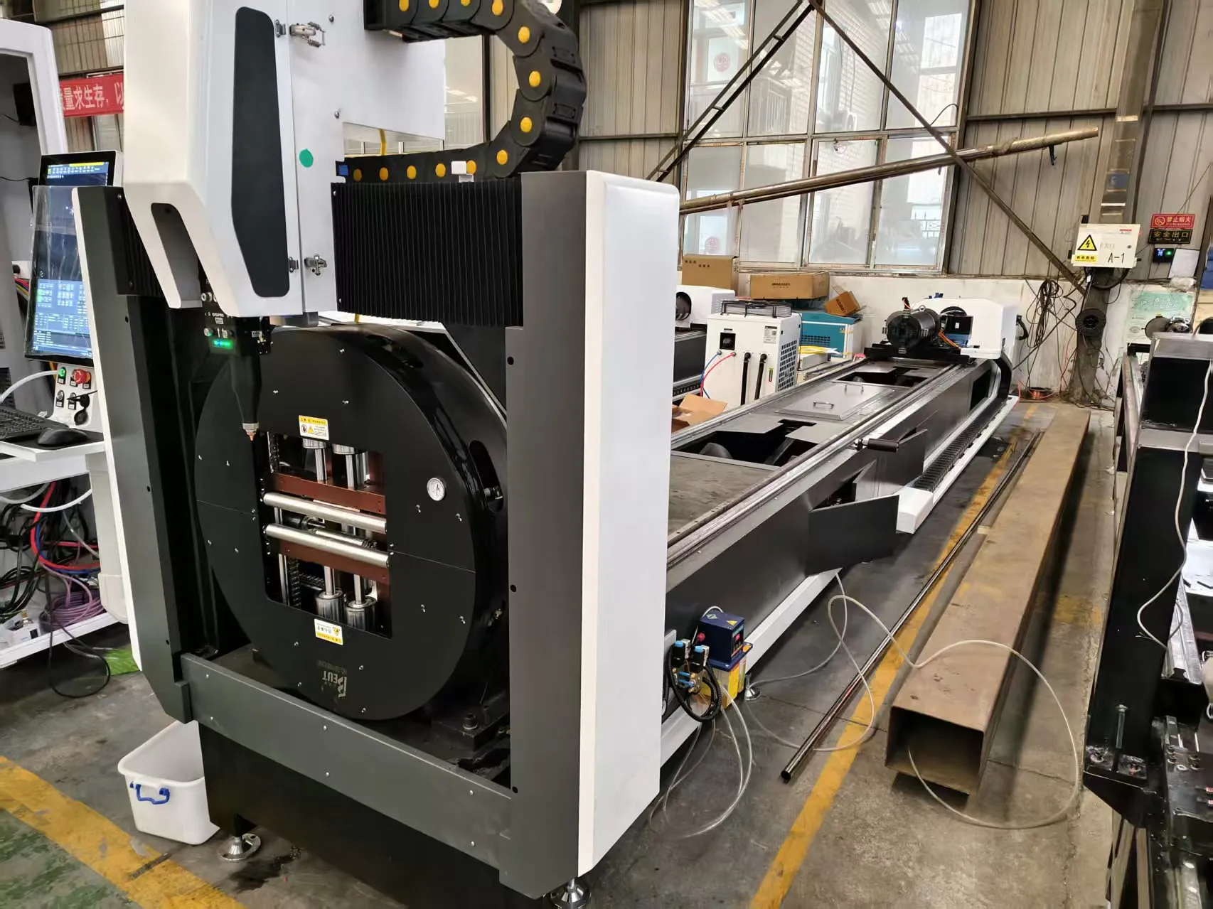
Technical Whitepaper: Optimizing Corrosion Resistant Duplex Stainless Steel Pipe Laser Cutting via Advanced Nesting & Common-Line Strategies
After two decades on the shop floor, I have watched the shift from abrasive saws and plasma arcs to fiber laser systems for processing duplex stainless steel (e.g., UNS S31803, S32205, S32750). The primary bottleneck is no longer the laser source itself—modern 6 kW to 12 kW fiber sources handle these alloys with acceptable edge quality. The real battle is material yield and cycle time reduction. For any fabricator dealing with corrosion resistant duplex stainless steel pipe laser cutting, the difference between profit and loss lies in how the nesting software handles the tube’s geometry and how the machine executes the cut sequence. This analysis focuses on the physics of the cut, the algorithm logic behind common-line cutting, and the specific parametric adjustments required for duplex grades.
Duplex stainless steel presents a unique challenge. Its high chromium (22-25%) and molybdenum (3-4%) content, combined with a dual austenitic-ferritic microstructure, create a viscous melt phase. Standard nitrogen assist gas at 1.2 MPa is insufficient; we typically run nitrogen at 1.5 MPa with a 0.2 mm to 0.3 mm nozzle standoff to eject the dross effectively. The laser frequency must be dialed to 5 kHz with a duty cycle of 60% to avoid micro-cracking in the heat-affected zone (HAZ). A continuous wave (CW) mode at 8 kW will cause excessive heat buildup, leading to sigma phase precipitation at the cut edge—a catastrophic failure point for corrosion resistance. We mitigate this by using a pulsed modulation at the corners and during pierce cycles, dropping the average power to 3.5 kW for the initial 200 ms pierce, then ramping to 6 kW for the cut.
Nesting Algorithms and Common-Line Logic for Tubular Profiles
The core of yield maximization for pipe is not 2D sheet nesting; it is rotational nesting and common-line cutting along the tube’s longitudinal axis. The software must account for the tube’s ovality tolerance (typically +/- 0.5 mm for standard ERW pipe) and the chuck’s pneumatic clamping pressure, which we set at 0.6 MPa to avoid deformation on thin-wall duplex (schedule 10S, 2.77 mm wall). The algorithm must calculate the optimal cut path to minimize the “lead-in” and “lead-out” tabs. For duplex, a poor lead-in causes a blowout at the start of the cut, wasting 150 mm of material per part.
Common-line cutting on a tube is a different beast compared to flat sheet. The laser head must cut two adjacent parts simultaneously along their shared boundary. This requires the CNC to execute a “double-pass” strategy: first pass at 4.5 kW to sever the first part, then a rapid retract and a second pass at 5.5 kW along the exact same path to separate the second part. The nesting algorithm must ensure the common line is oriented parallel to the tube’s axis to avoid angular distortion. We have achieved a 12% increase in material yield on a recent batch of S32205 pipes (OD 88.9 mm, 5.49 mm wall) by switching from single-part cutting to a 4-part common-line nest. The scrap rate dropped from 8.2% to 2.1%.
Comparative Analysis: Laser vs. Conventional Methods
The following table provides a direct technical comparison between conventional plasma cutting and the optimized fiber laser solution for duplex stainless steel pipe.
| Parameter | Conventional Plasma (HPR260) | Fiber Laser (6 kW, IPG) |
|---|---|---|
| Material Grade | UNS S31803 (Duplex) | UNS S31803 (Duplex) |
| Wall Thickness Range | 3.0 mm – 12.0 mm | 1.5 mm – 8.0 mm (optimal) |
| Cutting Speed (88.9 mm OD, 5.5 mm wall) | 450 mm/min | 1,800 mm/min |
| Kerf Width | 2.5 mm – 3.0 mm | 0.3 mm – 0.5 mm |
| Heat Affected Zone (HAZ) Depth | 1.2 mm – 1.8 mm | 0.1 mm – 0.3 mm |
| Assist Gas Consumption | O2 at 0.8 MPa (high flow) | N2 at 1.5 MPa (low flow) |
| Dross Formation | Heavy, requires grinding | Minimal, < 0.2 mm |
| Material Yield (per 6m pipe) | 82% (due to kerf & scrap) | 94% (with common-line nesting) |
| Edge Corrosion Resistance | Compromised (HAZ damage) | Maintained (low heat input) |
The data clearly shows that while plasma can handle thicker walls, the fiber laser excels in speed, precision, and material utilization. The reduction in kerf width alone—from 2.5 mm to 0.4 mm—saves 2.1 mm of material per cut line. Over a 6-meter pipe with 20 cuts, that is 42 mm of saved material. Multiply that by 500 pipes per shift, and the annual savings in duplex scrap (at $8/kg) becomes a significant line item.
Real-World Parametric Adjustments for Duplex
We recently commissioned a system for a pressure vessel manufacturer cutting S32750 super duplex. The initial parameters from the laser supplier were generic for stainless steel. We had to modify the following:
- Focus Position: Shifted from 0 mm (top surface) to -1.5 mm (inside the material) to improve the cut front stability. Duplex’s higher viscosity requires the beam to be slightly inside the kerf to avoid striations.
- Gas Nozzle: Switched from a standard 1.5 mm diameter nozzle to a 2.0 mm conical nozzle to increase gas flow velocity at the cut zone. This reduced dross adhesion by 70%.
- Chuck Pressure: Reduced from 0.8 MPa to 0.5 MPa for thin-wall (2.0 mm) duplex to prevent the tube from collapsing under clamping force. The nesting software had to be re-run with a new “clamping zone” exclusion to avoid cutting near the chuck jaws.
The common-line strategy on this job involved cutting a series of 300 mm long flanges from a single 6-meter pipe. The algorithm grouped four flanges into a single cut path, with the laser head moving continuously along the longitudinal axis. The cycle time per pipe dropped from 14 minutes (single cut) to 9.5 minutes (common-line), a 32% reduction. The scrap material from the lead-in tabs was reduced by 60%.
FAQ: Industrial B2B Procurement
1. What is the maximum wall thickness of duplex stainless steel pipe that can be cut with a fiber laser while maintaining corrosion resistance?
For S31803 and S32205 grades, we consistently achieve acceptable edge quality up to 8.0 mm wall thickness using a 6 kW fiber laser. Beyond that, the risk of HAZ cracking and sigma phase formation increases. For walls up to 12 mm, a 10 kW to 12 kW laser with a nitrogen assist at 1.8 MPa is required, but the cutting speed drops to 600 mm/min. We recommend a maximum of 8 mm for standard production to ensure the corrosion resistance of the cut edge meets ASTM A923 requirements.
2. How does the nesting software handle the ovality and straightness tolerances of ERW duplex pipe?
The advanced nesting algorithms we deploy use a “dynamic compensation” module. The machine first performs a laser scan of the pipe’s surface using the capacitive height sensor. This data is fed back to the nesting software, which adjusts the cut path in real-time to account for ovality up to 1.5 mm and bow up to 2 mm per meter. Without this, the common-line cut would misalign, causing a 0.5 mm step between parts. The software also automatically inserts a “skip-cut” command if the pipe deformation exceeds the chuck’s clamping compensation range (typically > 3 mm).
3. What is the typical payback period for upgrading from a plasma system to a fiber laser for duplex pipe cutting?
Based on our field data from three installations in the last 18 months, the payback period ranges from 14 to 20 months. The primary drivers are material yield improvement (12-15% reduction in scrap) and labor reduction (one operator can manage two laser cells vs. one plasma table). The assist gas cost for nitrogen is roughly 40% lower than the oxygen and argon mix used for plasma cutting duplex. The capital expenditure for a 6 kW fiber tube laser system with automated loading is approximately $380,000 to $520,000. At a production volume of 2,000 tons of duplex pipe per year, the annual savings in material and labor alone exceed $300,000.













