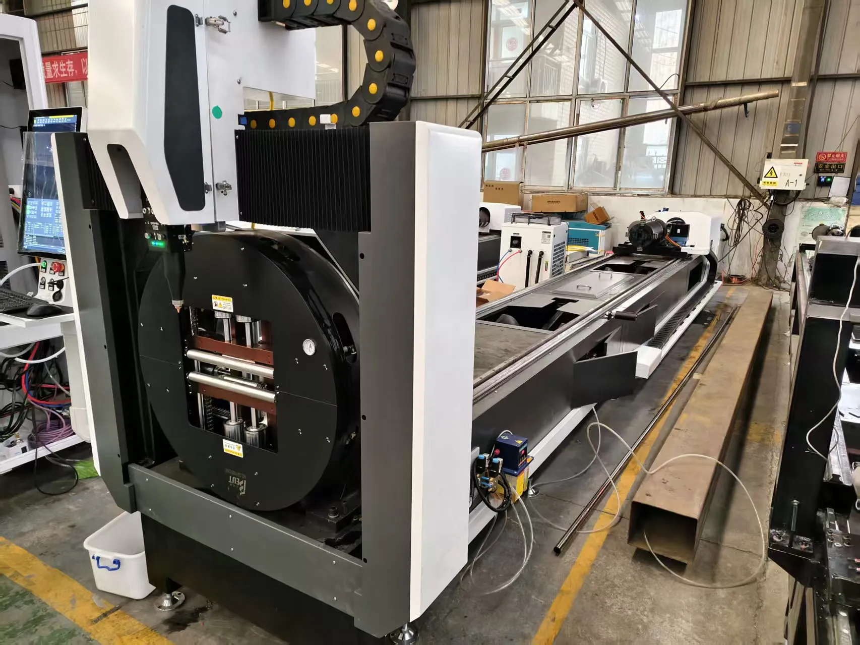
Shop-Floor Integration of Automatic Chuck Loading Tube Laser Systems for Mining Equipment Fabrication
Mining equipment fabrication lives or dies on structural tube integrity. Boom arms, jib sections, hydraulic cylinder guards, ROPS/FOPS frame members, and wear-plate standoffs are typically cut from heavy-wall seamless or DOM tube in grades such as S355JR, E355, 4140 chromoly, and abrasion-resistant variants. When a shop moves from manual saw-and-drill cells to an automatic chuck loading tube laser for mining equipment parts, the production bottleneck shifts from cutting speed to material handling and thermal control. This paper examines the workflow, tolerance stack-up, and absorption physics that determine whether a tube laser cell actually pays back on a mining fabrication floor.
Workflow Architecture: From Bundle to Finished Weldment
A functional automatic chuck loading cell is not a single machine — it is a synchronized sequence of material handling, clamping, cutting, and unloading stages. On a typical 6 m or 9 m tube laser with a front-loading bundle magazine, the cycle proceeds as follows:
- Bundle destacking: Chain-driven or scissor-lift magazine feeds raw tube (typically 20–24 ft lengths, 3–12 in OD) onto a V-roller infeed table. Misalignment here is the number one cause of chuck jaw crash and tube ovality damage.
- Pneumatic chuck clamping: A four-jaw or three-jaw self-centering chuck closes at 0.6–0.9 MPa (6–9 bar) for thin-wall DOM, and up to 1.4 MPa for heavy-wall 4140. Over-clamping crushes the tube; under-clamping allows axial slip during high-speed rotary cutting, which destroys kerf geometry.
- Servo-driven axial feed: The chuck carriage advances the tube through the cutting zone at feed rates matched to wall thickness — typically 0.8–2.5 m/min for 6 mm S355JR, dropping to 0.4 m/min for 12 mm wall.
- Cutting head positioning: Fiber laser head (typically 3–6 kW, 1070 nm wavelength) tracks the tube OD with capacitive height sensing. Standoff is held at 0.8–1.2 mm to maintain consistent focus.
- Part ejection and remnant handling: Cut parts drop to a collection conveyor; the remnant is either retracted or pushed out by a secondary chuck or push-rod system.
The critical insight from the floor: cycle time is rarely limited by the laser. It is limited by how fast the chuck can index, clamp, and release without inducing tube distortion. A well-tuned cell with 0.8 MPa clamping and 1.5 s chuck actuation can achieve 18–25 parts per hour on 4 in schedule-40 pipe with 6 mm wall.
Material Tolerance and Its Effect on Cut Quality
Mining tube stock is not precision-ground. Hot-finished seamless tube in S355JR commonly carries OD tolerance of ±1% and wall eccentricity up to 12.5%. This matters because the laser focus position is calibrated to a nominal OD. When eccentricity pushes the actual surface 0.5 mm closer to the nozzle, the kerf widens and dross formation increases on the bottom edge.
Practical countermeasures observed in production:
- Adaptive height control: Capacitive sensors sampling at 1 kHz compensate for OD runout up to 2 mm. Without this, kerf taper on 10 mm wall can exceed 0.3 mm per side.
- Chuck jaw selection: Serrated jaws grip better on hot-finished tube but mark the surface. For cosmetic mining parts (visible boom sections), polyurethane-padded jaws at reduced pressure (0.5 MPa) are used, accepting a slower feed rate.
- Wall thickness verification: Inline ultrasonic or laser triangulation gauges are increasingly integrated to reject out-of-tolerance tube before cutting, preventing scrapped parts and wasted nitrogen.
For SUS304 and Al6061 tube, thermal expansion coefficients differ significantly (17.3 µm/m·°C for 304 vs 23.1 µm/m·°C for 6061). On long parts, this means the cutting program must account for thermal growth during multi-pass cutting, or the final part length will drift by 0.5–1.2 mm over a 3 m cut.
Laser Absorption Efficiency: Wavelength, Assist Gas, and Material Response
Fiber laser absorption is not uniform across materials. At 1070 nm, the absorptivity of steel at room temperature is roughly 35–40%, rising to 60–70% once the melt pool forms. For Al6061, room-temperature absorptivity is only 5–8%, which is why aluminum tube cutting demands higher peak power and tighter focus.
Assist gas selection and delivery pressure directly govern cut quality:
- Nitrogen (N₂): Used for stainless and aluminum to prevent oxidation. Delivery pressure at the nozzle is typically 1.2–1.5 MPa for 6 mm SUS304, rising to 1.8 MPa for 10 mm. Purity must be 99.999% or higher; moisture contamination causes discoloration and porosity on weld-prep edges.
- Oxygen (O₂): Used for carbon steel (S355JR, 4140) to exploit exothermic reaction. Pressure is lower — 0.3–0.6 MPa — because the oxidation reaction supplies additional cutting energy. Too much O₂ causes a wide, dross-heavy kerf.
- Air (compressed): Acceptable only for thin-wall, non-critical parts. Not recommended for mining structural components due to nitride formation and reduced fatigue life.
Duty cycle matters here. A 6 kW fiber source running at 80% duty cycle on 12 mm S355JR will see thermal drift in the optical chain, shifting focus by 0.1–0.2 mm over a 4-hour shift. Active water-cooling of the cutting head and periodic focus recalibration are non-negotiable for tolerance-critical mining parts.
Comparative Technical Data: Legacy Methods vs. Automatic Chuck Tube Laser
| Parameter | Plasma Cutting (Manual) | Mechanical Sawing + Drilling | Automatic Chuck Tube Laser |
|---|---|---|---|
| Typical kerf width | 2.5–4.0 mm | 3.0–5.0 mm (blade) | 0.2–0.5 mm |
| Heat-affected zone (HAZ) | 1.5–3.0 mm | None (mechanical) | 0.1–0.3 mm |
| Dimensional tolerance | ±0.8 mm | ±0.5 mm | ±0.1 mm |
| Setup time per part | 15–30 min | 10–20 min | 2–5 min (program recall) |
| Assist gas pressure | 0.5–0.8 MPa (air/N₂) | N/A | 1.2–1.5 MPa (N₂) / 0.3–0.6 MPa (O₂) |
| Post-cut operations | Grinding, deburring | Deburring, chamfering | Minimal (weld-ready edge) |
| Throughput (4 in, 6 mm wall) | 8–12 parts/hr | 10–15 parts/hr | 18–25 parts/hr |
| Material utilization | 88–92% | 90–94% | 96–98% (nested) |
Procurement and Integration Considerations
When specifying an automatic chuck loading tube laser for mining equipment parts, the following parameters should be locked into the purchase agreement:
- Chuck clamping pressure range: minimum 0.4 MPa to maximum 1.6 MPa, with programmable ramp control.
- Laser source: 4–6 kW fiber, 1070 nm, with ≥ 80% duty cycle rating at 40°C ambient.
- Assist gas delivery: dual-line N₂/O₂ with 1.5 MPa regulated output and 99.999% purity filtration.
- Height sensing: capacitive, 1 kHz sampling, ±0.05 mm resolution.
- Tube capacity: 20–320 mm OD, 6 m standard length, with optional 9 m extension.
Floor layout must account for bundle storage, remnant return, and part sorting. A typical cell footprint is 12 m × 4 m, with 3 m clearance on the load side for forklift access.
FAQ: Industrial B2B Procurement
What tube diameter and wall thickness can an automatic chuck loading tube laser handle for mining parts?
Most industrial cells handle 20–320 mm OD with wall thickness from 1 mm to 12 mm in carbon steel, and up to 8 mm in stainless or aluminum. For heavy-wall 4140 chromoly above 12 mm, a higher-power source (8–12 kW) and reduced feed rate are required.
How does laser absorption efficiency affect cutting speed on S355JR versus SUS304?
S355JR absorbs 1070 nm energy more readily due to its iron content and oxide-forming behavior, allowing faster cutting with O₂ assist. SUS304 requires N₂ assist at 1.2–1.5 MPa and runs 20–30% slower due to higher reflectivity and lower thermal conductivity-driven melt efficiency.
What pneumatic clamping pressure is recommended to avoid tube deformation?
For thin-wall DOM tube (≤ 3 mm), clamp at 0.4–0.6 MPa with padded jaws. For heavy-wall tube (≥ 8 mm), 1.0–1.4 MPa is acceptable. Always verify with a test cut and ovality measurement before committing to production pressure settings.













