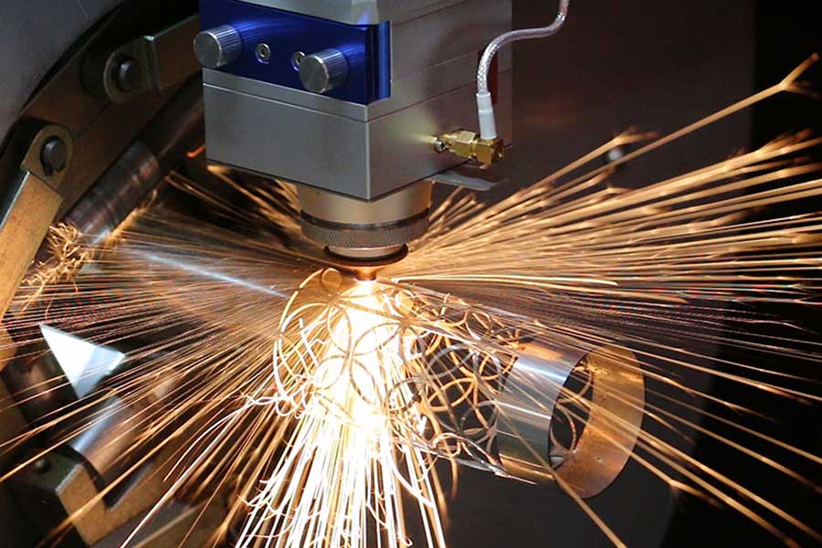
Automated Tube Laser Loading Systems in Motorcycle Frame Production: Nesting Algorithms, Common-Line Cutting, and Yield Physics
Motorcycle frame fabrication has shifted from jig-welded chromoly assemblies to high-tolerance structural networks built from S355JR, SUS304, and Al6061-T6 tube stock. The bottleneck is no longer the laser resonator—it is the material handling interface and the software that decides where the beam actually travels. A properly specified automated tube laser loading system for motorcycle frame production eliminates the manual bundle-to-chuck cycle that historically consumed 22–35% of available cutting time on a 6 kW fiber source. When that loader is paired with nesting logic that respects kerf physics and remnant geometry, yield on 6-meter tube stock climbs from a baseline 71–76% to 88–92% on mixed back-bone, cradle, and subframe part families.
Why Manual Loading Kills Yield Before the Beam Fires
On a 3-chuck, 6 kW tube machine running 1.5–3.0 mm wall S355JR, the resonator is rarely the constraint. The constraint is the gap between cut cycles. Manual operators load one tube at a time, index it against a mechanical stop, and re-zero the chuck jaw pressure—typically 0.6–0.8 MPa on pneumatic scroll chucks for thin-wall tube. Every re-clamp introduces runout variance of 0.15–0.35 mm, which forces the CAM programmer to add safety margins around common-line features. Those margins are pure scrap.
An automated loader with a bundle magazine (12–24 tubes per cassette) and servo-driven V-roller feed changes the economics. Chuck pressure is regulated to 0.9 MPa on the rear chuck and 0.7 MPa on the front to prevent tube crushing on Al6061-T6 while maintaining grip on SUS304. The loader presents tube ends to within ±0.1 mm of the zero datum, which lets the nesting engine eliminate the conservative offset that manual setups demand.
Nesting Algorithms: The Real Yield Lever
Motorcycle frames are a nightmare for nesting because part lengths are irregular—a steering head gusset at 180 mm, a swingarm pivot tube at 420 mm, a downtube at 1,150 mm. A naive first-fit-decreasing algorithm wastes 15–20% on remnant drops. Production-grade nesting for tube laser uses a hybrid approach:
- Genetic algorithm seeding with a population of 200–400 layouts, mutating part order across a 6,000 mm virtual tube.
- Common-line constraint enforcement so adjacent parts share a single kerf pass instead of two.
- Remnant re-injection: drops longer than 350 mm are returned to the queue as new stock, not scrapped.
- Grain and weld-seam awareness for SUS304 tube, where the weld seam must be rotated to the neutral axis before cutting.
On a typical 250cc–450cc frame BOM, this logic pushes tubes-per-frame from 4.2 to 3.6, a 14% material reduction that compounds across a 40,000-unit annual volume.
Common-Line Cutting: Kerf Physics and Duty Cycle
Common-line cutting on tube is not the same as on flat sheet. The curvature of the tube means the beam enters at a varying angle, and the kerf width shifts from 0.15 mm at the crown to 0.28 mm at the tangent. To hold a shared edge between two parts, the controller must compensate with dynamic focus and a reduced duty cycle.
Real parameters on 2.0 mm S355JR with a 6 kW source:
- Nitrogen assist at 1.4 MPa for clean edges on visible frame surfaces.
- Oxygen at 1.2 MPa only for hidden gussets where oxide is acceptable.
- Frequency 1,200–1,800 Hz, duty cycle 65–75% on common-line passes to prevent dross adhesion at the shared kerf.
- Feed rate 4.2 m/min on straight common-line, dropping to 2.8 m/min on the curved transition zones.
The payoff is measurable: common-line cutting on a swingarm pivot bracket pair reduces pierce count from 6 to 3 and cuts cycle time by 18 seconds per tube.
Comparative Technical Data: Legacy vs. Automated Laser
| Parameter | Plasma / Mechanical Saw (Legacy) | Automated Tube Laser (Current) |
|---|---|---|
| Material yield on 6 m tube | 68–74% | 88–92% |
| Kerf width | 1.5–3.0 mm (plasma) | 0.15–0.28 mm |
| Heat-affected zone | 0.8–2.5 mm | 0.05–0.12 mm |
| Chuck / clamping pressure | N/A (fixture clamp) | 0.7–0.9 MPa pneumatic |
| Assist gas | Compressed air / O₂ | N₂ at 1.4 MPa, O₂ at 1.2 MPa |
| Per-tube load time | 45–90 s manual | 8–14 s automated |
| Dimensional repeatability | ±0.5 mm | ±0.08 mm |
| Post-process (deburr) | Required, 2–4 min/part | Minimal, <30 s/part |
Material Yield Maximization: The Compounding Effect
Yield is not a single number. It is the product of nesting efficiency, kerf loss, remnant recovery, and scrap rate. On a 450cc frame program running S355JR and SUS304 in a 70/30 mix, the automated system delivers:
- Nesting efficiency: 91.4%
- Kerf loss: 1.8%
- Remnant recovery: 4.2% returned to stock
- Scrap from misload: 0.3% (down from 3.1% manual)
Net yield lands at 89.5%, translating to roughly 118 kg of steel saved per 1,000 frames. At current S355JR pricing, that is a direct material cost reduction that pays back the loader investment in 14–18 months on a two-shift operation.
Integration Notes for Frame Shops
The loader must communicate with the nesting engine via OPC-UA or a proprietary MES handshake. When the CAM software re-nests mid-shift due to a BOM change, the loader must re-sequence the cassette without operator intervention. This requires a tube-tracking database keyed to the bundle ID, not just the part number. Shops that skip this step lose 6–9% of the yield gain to rework and misload.
FAQ: Procurement and Integration
What tube diameter range can an automated loader handle for motorcycle frame production?
Most production loaders cover 16 mm to 120 mm OD with wall thickness from 0.8 mm to 6.0 mm. For motorcycle frames, the practical sweet spot is 22–76 mm OD, with chuck jaw sets swapped for thin-wall SUS304 to prevent ovalization at 0.7 MPa clamping pressure.
Does common-line cutting work on curved tube sections or only straight runs?
It works on both, but curved sections require dynamic focus compensation and a reduced duty cycle of 60–70% to prevent dross at the shared kerf. Straight common-line runs on S355JR at 2.0 mm can hold 4.2 m/min with nitrogen at 1.4 MPa.
What is the realistic payback period for an automated tube laser loading system?
On a two-shift motorcycle frame line running 30,000–50,000 units annually, payback ranges from 14 to 20 months. The dominant factors are material yield gain (12–18 percentage points over plasma/saw) and the elimination of 3–5 manual operators per shift.













