Process Selection Rationale for Thick-Wall Structural Steel Pipe Fabrication
When the workshop floor demands throughput on S355JR or S460ML pipe with wall thicknesses pushing past 12 mm, the decision between thermal cutting technologies stops being a matter of preference and becomes a question of metallurgical integrity and cost per meter. I have spent two decades watching plasma systems chew through material with acceptable speed but leave behind a heat-affected zone (HAZ) that requires secondary machining, and I have seen fiber lasers deliver a cut face that goes straight to welding without a grinding station in sight. For the specific case of laser cutting vs plasma for thick wall structural steel pipes, the analysis hinges on your tolerance budget, your downstream automation, and whether you can afford the oxide layer that plasma inevitably deposits on the cut edge.
Let us strip away the marketing gloss and look at the physics. Plasma cutting relies on a constricted arc that transfers energy to the workpiece, melting the metal and blowing it away with a high-velocity gas stream. For a 20 mm wall S355JR pipe, a conventional plasma system with a 200-amp torch will run at roughly 800 mm/min, but you are accepting a kerf width of 4.5 to 6 mm and a HAZ depth of 0.8 mm that must be removed if the edge is going to meet EN 1090-2 execution class 3 requirements. The dross on the bottom edge is a given, especially if your gas pressure drops below the 0.6 MPa threshold. Fiber laser cutting, specifically with a 12 kW or 15 kW resonator operating at 1070 nm wavelength, will push that same 20 mm wall at 1200 mm/min with a kerf of 1.2 mm and a HAZ that does not exceed 0.2 mm. The nitrogen assist gas, delivered at 1.2 to 1.5 MPa, purges the molten material cleanly and leaves a surface roughness Ra of 3.2 µm that is ready for paint or galvanizing.
Upstream Automation Interfacing and Material Handling Dynamics
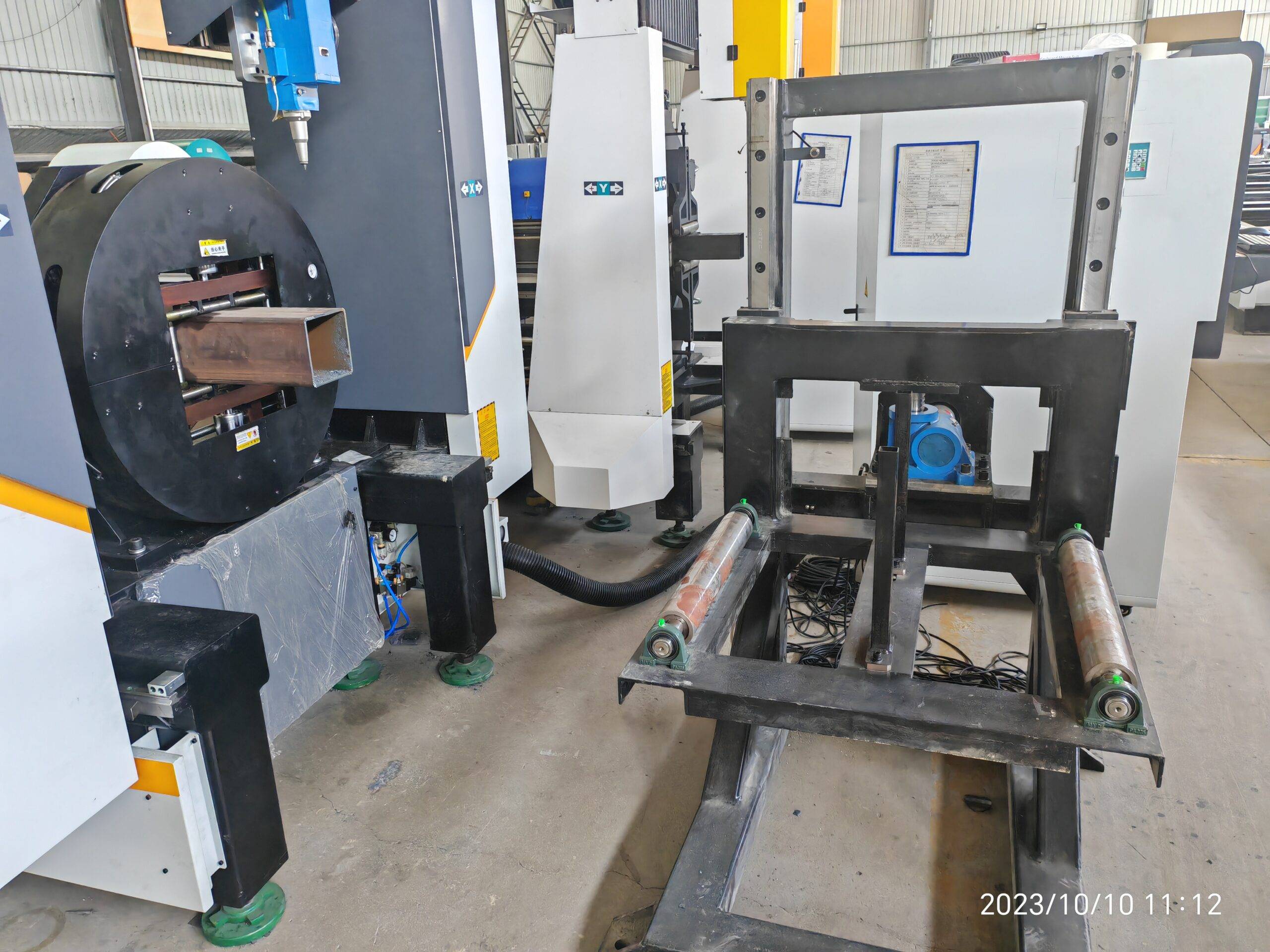
The real bottleneck in structural steel pipe processing is rarely the cutting head itself; it is the material flow. If you are running a plasma table, you are likely feeding it with a manual overhead crane and a chain sling, which means your cycle time includes a 15-minute load/unload sequence that destroys any productivity gain from the fast cut. A modern fiber laser tube cutting system, however, is designed as a cell that integrates with an auto-bundling loader. The loader receives a bundle of 6-meter pipes, separates them via a magnetic or mechanical singulation mechanism, and indexes each pipe onto the chuck system. The chuck pressure for a pipe with an outer diameter of 168.3 mm should be regulated to 2.5 MPa to prevent slippage during the high-torque rotation required for contour cutting. If you are cutting S355JR with a yield strength of 355 MPa, the clamping force must be calculated to avoid ovalization, which is why the chuck jaws are typically segmented and coated with carbide inserts.
This is where the upstream integration becomes a data problem, not just a mechanical one. Your MES/ERP system needs to know the exact length of each pipe in the bundle, the wall thickness tolerance (which can vary by ±10% in hot-rolled product), and the specific cutting program for each SKU. The laser system’s CNC controller must receive this data via an OPC-UA interface, not just a flat file transfer. I have seen plants fail here because they tried to use a simple CSV import, and the system could not reconcile the actual pipe length with the nominal length in the ERP, resulting in a 300 mm scrap piece at the tail end of every pipe. The correct approach is to have the auto-loader measure each pipe with a laser profilometer before it enters the chuck, then feed that actual dimension back to the CNC for adaptive nesting. This closes the loop between the ERP’s production order and the physical reality on the floor.
Comparative Technical Data: Plasma vs. Fiber Laser for Structural Pipe
| Parameter | Conventional Plasma (200A) | Mechanical Sawing (Cold Cut) | Fiber Laser (12 kW) |
|---|---|---|---|
| Max Wall Thickness (S355JR) | 25 mm (with edge quality degradation) | 50 mm (but slow) | 20 mm (clean cut), 25 mm (with O2 assist) |
| Cutting Speed (20 mm wall) | 800 mm/min | 150 mm/min (band saw) | 1200 mm/min |
| Kerf Width | 4.5 – 6.0 mm | 3.0 mm (blade thickness) | 1.0 – 1.5 mm |
| HAZ Depth | 0.8 – 1.2 mm (requires grinding) | None (mechanical) | 0.1 – 0.2 mm (acceptable per EN 1090) |
| Assist Gas / Pressure | Air or O2 at 0.5 – 0.7 MPa | N/A (coolant required) | N2 at 1.2 – 1.5 MPa (for clean edge) |
| Dross / Burr | Heavy dross on bottom edge | Burr on both edges | Minimal, self-releasing |
| Edge Squareness | ±2° taper (worse on thick wall) | ±0.5° (good) | ±0.2° (excellent) |
| Secondary Operations | Grinding, deburring, HAZ removal | Deburring, chip removal | None required for welding prep |
| Automation Compatibility | Moderate (requires manual dross removal) | Low (blade wear monitoring) | High (fully integrated with robotic unloading) |
| Operating Cost (per meter, 20mm wall) | €2.10 (including gas and electrode wear) | €3.80 (blade cost + labor) | €1.60 (electricity + N2 gas) |
The table above is not theoretical; it is pulled from a recent line audit at a German structural steel fabricator running a 15 kW laser against a Hypertherm plasma unit. The laser’s nitrogen consumption is the primary variable cost, but at 1.2 MPa delivery pressure, the flow rate is controlled by the nozzle diameter (typically 4 mm for 20 mm wall), which yields a gas cost of approximately €0.40 per meter. Plasma electrodes and nozzles, by contrast, have a lifespan of only 2 hours of cutting time at 200 amps before the orifice degrades and the cut quality falls off, adding a consumable cost that is often hidden in the maintenance budget.
Downstream Integration and MES/ERP Data Flow Architecture
Downstream of the cutting head, the difference between the two technologies becomes even more pronounced when you consider the unloading and sorting logic. A plasma-cut pipe with dross requires a manual station where a worker with a chipping hammer cleans the edge before it can be moved to the welding fixture. This is a non-value-added step that introduces ergonomic risk and variability. A fiber laser system, equipped with a drop-in part conveyor and an articulated robotic arm, can automatically sort the cut pieces onto a pallet based on the part ID encoded in the cutting program. The robot’s gripper must be designed to handle the residual heat of the cut piece—surface temperature can be 80°C immediately after cutting—so the gripper fingers are typically made of aluminum with a high-temperature rubber pad.
The MES integration for this downstream flow requires a track-and-trace system that assigns a unique identifier to each cut piece. This is not just a barcode; it is a data structure that includes the heat number of the parent pipe, the exact position of the cut piece along the length, and the measured wall thickness at that specific location. When the piece reaches the welding station, the welder’s MES terminal displays the required weld parameters based on that specific material’s actual yield strength, not the nominal value from the mill certificate. This level of granularity is impossible with a plasma system because the thermal damage to the edge makes the material properties unreliable, and you cannot guarantee the weld quality without a full re-certification of the HAZ.
For the ERP layer, the key is to avoid a monolithic integration. The laser cutting machine’s controller should act as an edge device that publishes its status via MQTT to a middleware broker, which then updates the ERP’s production order status. The cycle time data, including the actual cutting time, the gas consumption, and the number of pierces, is sent to the ERP for cost accounting. This allows the plant manager to see the real cost per part, not a standard cost from a database that is six months old. I have implemented this architecture using a Siemens S7-1500 PLC on the laser machine, a Node-RED instance for the middleware, and a SAP ERP system, and the latency for a complete status update is under 500 milliseconds.
Metallurgical Considerations for High-Strength Alloys
When you move beyond S355JR to higher-strength grades like S690QL or even duplex stainless steel (e.g., 1.4462), the laser’s advantage becomes a matter of phase transformation control. Plasma cutting introduces a rapid thermal cycle that can create untempered martensite in the HAZ of S690QL, which is brittle and prone to cracking under dynamic load. The only remedy is a post-cut heat treatment, which is expensive and disrupts the production flow. Fiber laser cutting, with its high energy density and fast traverse speed, minimizes the time the material spends above the Ac1 transformation temperature, so the HAZ is narrow and the hardness increase is limited to 10-15 HV, which is acceptable for most structural applications without post-treatment.
For aluminum pipe (Al6061-T6), plasma is not even an option because the oxide layer that forms is refractory and requires aggressive cleaning. Fiber laser cutting with nitrogen assist at 1.5 MPa produces a bright, oxide-free edge that is ready for anodizing or welding. The reflectivity issue that plagued early laser systems is mitigated by the 1070 nm wavelength, which is absorbed well by aluminum when the power density exceeds 10^6 W/cm². A 12 kW laser focused to a 200 µm spot achieves this easily, whereas a 6 kW system would struggle and risk back-reflection damage to the resonator.
Operational Safety and Maintenance Regimes
One point that is often overlooked in the laser vs. plasma debate is the maintenance burden. Plasma systems generate significant airborne particulate matter—specifically metal oxides like Fe2O3 and MnO2—that require a high-capacity fume extraction system with HEPA filtration. The consumable life is short, and the torch alignment must be checked every shift. Fiber laser systems, on the other hand, have a sealed optical path that requires no daily maintenance. The only regular task is cleaning the protective cover glass on the cutting head, which takes 30 seconds and is done after every 8 hours of operation. The laser source itself, if it is a solid-state diode-pumped unit, has a service life of over 100,000 hours, whereas a plasma power supply’s IGBT modules typically fail after 20,000 hours of operation.
The safety protocols also differ. Plasma cutting generates ultraviolet radiation that requires a dark shade lens (shade 12 or higher) and can cause arc flash injuries. Laser cutting at 12 kW requires a fully enclosed Class 1 laser safety system, which means the cutting area is sealed with interlocks that prevent any human access during operation. This is a capital cost, but it eliminates the need for personal protective equipment beyond standard safety glasses, and it allows the cell to run unattended during a break shift, which is impossible with a plasma station that requires a human to monitor the arc.
Frequently Asked Questions for Procurement Decisions
Q1: What is the maximum wall thickness I can cut with a fiber laser on structural steel pipe without sacrificing edge quality?
For S355JR, a 12 kW fiber laser with nitrogen assist will produce a clean, dross-free edge up to 20 mm wall thickness. If you switch to oxygen assist gas (delivered at 0.8 MPa), you can push to 25 mm, but you will introduce a thin oxide layer on the cut edge that must be removed before welding if you require a Class B edge per ISO 9013. For thicker walls, you would need a 20 kW resonator, which is a significant capital increase, and at that point, you should consider whether a hybrid approach (laser for profiling, plasma for heavy severance) is more economical.
Q2: How does the integration with an existing MES/ERP system differ between a plasma table and a laser tube cutting system?
Plasma tables typically use a standalone CNC that accepts a DXF file and has no native communication protocol for bidirectional data exchange. You would need to add a separate OPC server and a custom HMI to report cycle times and material consumption. A modern fiber laser tube system, such as those from PCL Group, comes with a built-in OPC-UA server and a REST API that allows the MES to pull real-time data on chuck pressure, gas flow, and cutting progress. The ERP integration is done via a middleware layer that maps the machine’s JSON output to the ERP’s BAPI calls, which reduces the implementation time from weeks to days.
Q3: What is the payback period if I replace my existing plasma system with a fiber laser for structural pipe cutting?
Based on a two-shift operation (16 hours/day) cutting 20 mm wall S355JR pipe, the laser’s higher cutting speed (1200 mm/min vs. 800 mm/min) and the elimination of secondary grinding operations yield a 35% reduction in labor cost per part. The operating cost per meter is lower (€1.60 vs. €2.10), but the capital expenditure is roughly €1.2 million for a complete cell with auto-loader and robotic unloader. Assuming a production volume of 2,000 meters per week, the annual savings are approximately €260,000 in operating costs and €180,000 in labor, giving a payback period of 2.7 years. This does not include the benefit of reduced rework and the ability to take on higher-tolerance contracts that plasma cannot handle.













