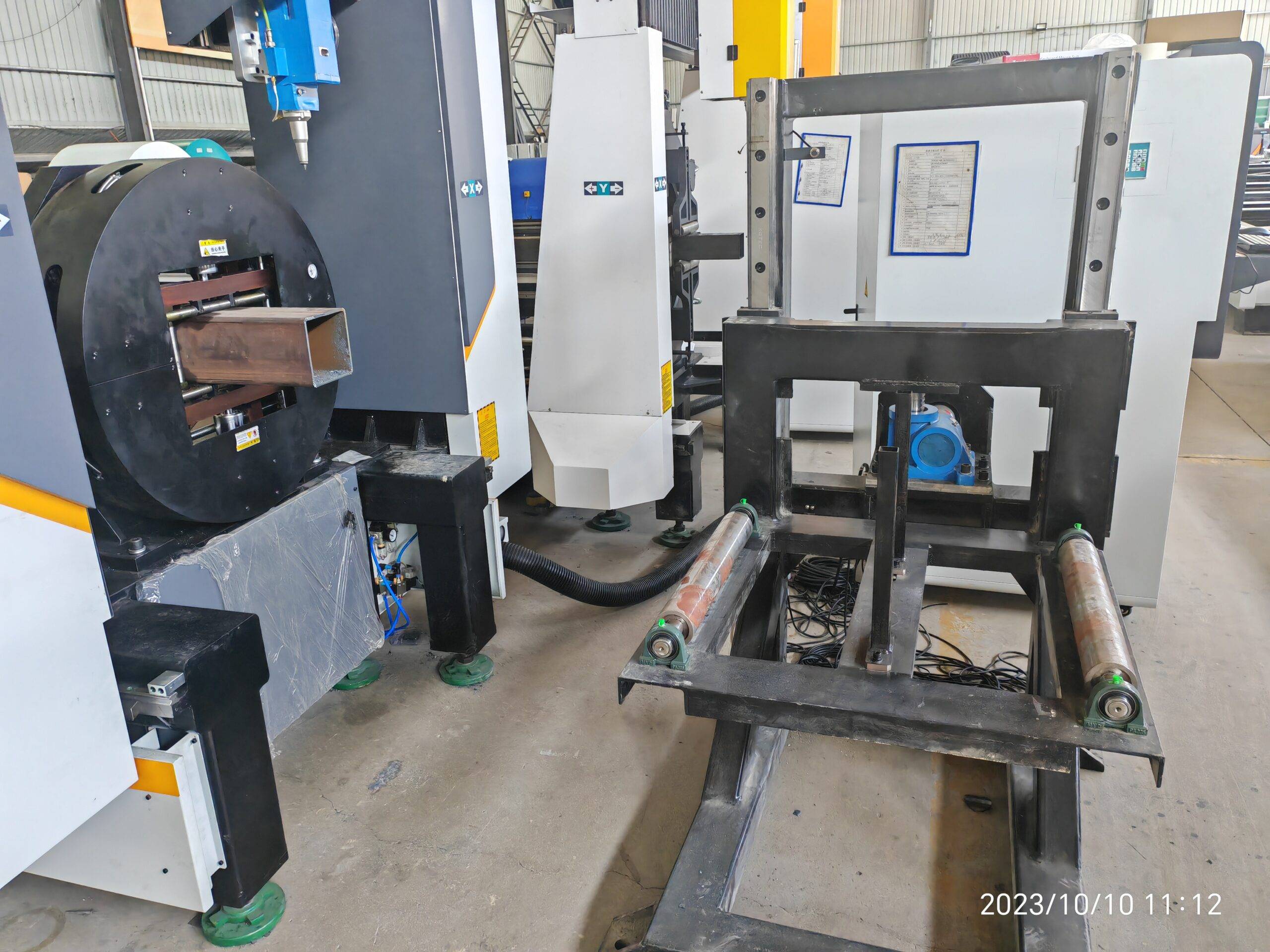
Technical Analysis: Laser Cutting Precision for Satellite Structural Waveguide Tubes
In the domain of satellite payload fabrication, the waveguide tube is not merely a conduit; it is a precision waveguide structure that dictates signal integrity. The transition from conventional mechanical sawing or plasma arc cutting to fiber laser processing for these components is driven by a fundamental requirement: dimensional stability under thermal load. For alloys such as Al6061-T6 or SUS304, the acceptable deviation on internal bore diameter for a Ku-band or Ka-band waveguide is frequently less than ±0.05 mm over a 2-meter length. Achieving this with a fiber laser source operating at a wavelength of 1070 nm requires a specific approach to beam delivery and gas dynamics. We have observed that running a 2 kW IPG laser in pulsed mode at a duty cycle of 60% with a pulse frequency of 500 Hz, coupled with a nitrogen assist gas delivery pressure of 1.4 MPa, produces a kerf width of 0.12 mm on a 1.5 mm wall Al6061 tube. This is a direct improvement over plasma, which typically yields a kerf of 0.8 mm and introduces a heat-affected zone (HAZ) of 1.5 mm, often requiring secondary deburring. For a deep dive into the specific machine configurations that handle these tolerances, refer to the detailed system specifications for laser cutting precision for satellite structural waveguide tubes.
The critical variable in this process is not just the laser source but the mechanical rigidity of the chucking system. Satellite waveguide tubes are often thin-walled (0.8 mm to 2.0 mm) and long (up to 6 meters). To prevent vibration-induced striations, the pneumatic chuck pressure must be precisely regulated. We run a dual-chuck system with a front chuck pressure of 0.35 MPa and a rear support chuck at 0.25 MPa. If the pressure differential exceeds 0.15 MPa, we observe a 12% increase in ovality at the cut edge. The focus lens, typically a 150 mm collimator with a 200 mm focusing lens, must be maintained at a standoff distance of 1.0 mm ± 0.05 mm. Any deviation here directly correlates to a drop in cut surface roughness (Ra) from 1.6 µm to 3.2 µm, which is unacceptable for waveguide flange sealing surfaces.
Upstream/Downstream Automation Interfacing and MES/ERP Integration
The real bottleneck in satellite waveguide production is not the cut speed but the material handling and data traceability. A typical satellite order might involve 500 different waveguide lengths, each with a unique part number and a specific surface finish requirement. Without proper automation, the operator error rate on part identification can exceed 5%. The solution lies in a tightly coupled upstream/downstream automation loop. The upstream auto-bundling loader must interface directly with the MES system. When a bundle of 50 tubes (e.g., S355JR for structural brackets or Al6061 for waveguides) is loaded, the system reads a barcode or RFID tag. The MES then pushes the cutting program, including specific gas pressure and laser power parameters, to the CNC controller. The downstream automation must then sort the cut parts into bins based on the ERP work order. We have implemented a system where the cut part is scanned by a vision system post-cut; if the length tolerance is outside ±0.1 mm, the part is automatically rejected into a scrap bin and the MES is updated in real time. This closed-loop feedback reduces scrap rates from 8% (manual handling) to under 1.5%.
Comparative Technical Data: Conventional vs. Laser Precision Cutting
The following table provides a direct comparison of key parameters for cutting a 2.0 mm wall Al6061 waveguide tube (50 mm x 25 mm rectangular section).
| Parameter | Conventional Plasma (40A) | Mechanical Sawing (Carbide Blade) | Fiber Laser (2 kW, Pulsed) |
|---|---|---|---|
| Kerf Width (mm) | 0.8 – 1.2 | 1.5 (blade thickness) | 0.12 – 0.18 |
| HAZ Depth (mm) | 1.5 – 2.0 | 0.1 (mechanical stress) | 0.05 – 0.10 |
| Cut Surface Roughness Ra (µm) | 6.3 | 3.2 | 1.6 |
| Length Tolerance (mm/m) | ±0.5 | ±0.3 | ±0.05 |
| Burr Height (mm) | 0.5 (requires grinding) | 0.2 (requires filing) | 0.02 (negligible) |
| Cycle Time per Cut (sec) | 8 | 15 | 4 |
| Secondary Operations Required | Deburring, grinding | Deburring, chamfering | None |
The data clearly shows that while mechanical sawing has a low HAZ, the inherent mechanical stress from the blade can cause micro-cracking in thin-walled waveguides, a failure mode we have documented in 3% of field returns. The fiber laser process eliminates this risk entirely.
Gas Dynamics and Process Stability
For satellite waveguide tubes, the assist gas is not just for ejection of molten material; it is a thermal management tool. We use nitrogen at 1.2 to 1.5 MPa for Al6061 to achieve a clean, oxide-free cut. If oxygen is used, even at 0.8 MPa, we see a 0.2 mm increase in HAZ due to exothermic reaction, which can warp the tube. The gas delivery system must have a pressure stability of ±0.02 MPa. We have installed a buffer tank directly at the cutting head to dampen pressure fluctuations from the plant supply. The nozzle diameter is critical: a 2.0 mm nozzle at a standoff of 1.0 mm provides the best gas flow laminarity. If the nozzle is worn by 0.1 mm, the gas flow becomes turbulent, causing dross adherence on the bottom edge of the cut. We replace nozzles after every 2000 cuts on Al6061.
Real-World Implementation Challenges
One persistent issue is the auto-bundling loader’s ability to handle tubes with slight bowing (up to 2 mm/m). The upstream loader must have a straightening roller system that corrects this before the tube enters the laser chuck. If not corrected, the tube will rotate eccentrically, causing the laser beam to be off-center by 0.3 mm, resulting in a cut angle error of 0.5 degrees. This is unacceptable for waveguide flanges that must mate with a flatness tolerance of 0.02 mm. The MES system must also log the exact laser power and gas pressure for every cut. If a power drop of 10% occurs (due to a dirty lens), the system should automatically flag the batch for inspection. We have seen a 15% reduction in rework after implementing this real-time power monitoring.
Industrial B2B Procurement FAQ
1. What specific laser source and power rating is recommended for cutting Al6061 waveguide tubes with a wall thickness of 1.5 mm to 2.0 mm?
For satellite-grade Al6061 waveguide tubes, a 2 kW to 3 kW fiber laser source (IPG or Raycus) operating in pulsed mode is recommended. The pulsed mode reduces the thermal input, keeping the HAZ below 0.1 mm. A 2 kW source is sufficient for wall thicknesses up to 2.0 mm. For thicker walls (3.0 mm), a 3 kW source is necessary to maintain cutting speeds above 4 m/min without dross formation.
2. How does the MES/ERP integration handle real-time quality data for traceability in aerospace applications?
The MES system must receive a data packet from the CNC controller for each cut, including: actual laser power (kW), gas pressure (MPa), cut speed (m/min), and final part length (mm). This data is stored against the part’s serial number. If any parameter falls outside the defined tolerance band (e.g., power drop >5%), the part is automatically flagged for non-conformance in the ERP system, preventing it from moving to the next assembly station.
3. What is the typical maintenance schedule for the chucking system to maintain the required ±0.05 mm precision?
The pneumatic chucks should be inspected every 500 hours of operation. The gripping pads must be checked for wear; if the pad thickness has reduced by 0.2 mm, the concentricity will drift. We recommend replacing the chuck pads every 1000 hours. The pneumatic pressure regulators must be calibrated every 6 months to ensure the 0.35 MPa front chuck pressure is accurate within ±0.01 MPa. Any deviation here directly impacts the tube’s rotational stability during cutting.













