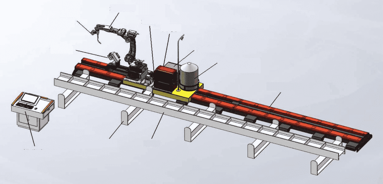
Industrial Pipe Laser Processing Line for Shipbuilding Yards: A Technical Analysis of Clamping Dynamics, Rotary Synchronization, and Thin-Wall Deformation Control
The transition from conventional thermal cutting and mechanical sawing to fiber laser processing for marine pipe spooling is not a trend; it is a mathematical necessity. When a yard is processing S355JR and S355J2H structural steel pipes with wall thicknesses ranging from 4.5 mm to 25 mm, the tolerance stack-up from plasma dross and saw blade deflection creates costly rework in the welding bay. For yards upgrading their throughput, integrating a dedicated industrial pipe laser processing line for shipbuilding yards addresses the core bottleneck: the interface between the rotary axis and the material clamping system. This analysis focuses specifically on the mechanical dynamics that dictate cut quality, not just the laser source itself.
In a typical shipyard environment, the pipe lengths vary from 6 to 12 meters, with diameters ranging from 60.3 mm OD to 406.4 mm OD. The primary failure mode in automated laser tube cutting is not laser power insufficiency, but rather torsional wind-up and axial slippage during high-speed rotary interpolation. We must examine the pneumatic chuck clamping dynamics as the first line of defense against geometric error.
Pneumatic Chuck Clamping Dynamics: Force Calculation and Material Yield Limits
Standard three-jaw chucks on generic tube lasers are inadequate for shipbuilding grades. The issue is the radial force distribution. For a 168.3 mm OD pipe in S355JR (yield strength approx. 355 MPa), the clamping force must be sufficient to overcome the tangential cutting force without inducing plastic deformation on the inner diameter. We calculate the required radial force (F_r) using the coefficient of friction (μ ≈ 0.15 for carbide-tipped serrated jaws on mill scale) and the maximum tangential force (F_t) from the cutting process. For a 6 kW laser cutting 12 mm wall thickness at 1.2 m/min, the reactive torque is significant.
However, the danger lies in over-clamping. If the pneumatic pressure exceeds 0.6 MPa on a thin-wall pipe (e.g., 60.3 mm OD x 3.2 mm wall in SUS304), the chuck jaws will induce lobing—a tri-lobed deformation that causes the rotary axis to run out of true center. The solution is a dual-pressure clamping circuit. The chuck must engage with a high-pressure “grip” phase (0.5 MPa) to seat the jaws, then automatically reduce to a “cutting hold” phase (0.25 MPa) to prevent ovality. This is not a software feature; it requires a proportional pressure regulator with a response time under 50 ms, synchronized with the Z-axis plunge feed.
Rotary Axis Synchronization: The Inertia Mismatch Problem
The rotary axis (A-axis) and the linear axis (X-axis) must operate as a single kinematic chain. In shipbuilding, we often deal with eccentric pipes—pipes that have a slight bend from storage or transport. A standard servo motor with a gearbox will struggle to maintain constant surface speed if the center of gravity is offset. This is where the concept of “torque feed-forward” becomes critical. The CNC controller must calculate the inertia mismatch (J_load / J_motor) in real-time. If the ratio exceeds 4:1, we see oscillation at the cut kerf, leading to a “scalloped” edge profile.
For a 406.4 mm OD pipe weighing 300 kg per 12-meter section, the chuck and spindle assembly must have a moment of inertia rating that matches the load. We specify a dual-motor anti-backlash drive system—one motor driving the chuck, one motor driving a support steady rest—with electronic gearing via a 22-bit absolute encoder. The synchronization error must be maintained below ±0.01 degrees to ensure the laser head’s focus position remains within the Rayleigh length (typically ±0.5 mm for a 200 mm focal length lens). If the rotary axis lags by even 0.1 degrees on a 400 mm diameter pipe, the tangential velocity error is 0.7 mm/s, which is enough to cause striation marks on the cut edge.
Thin-Wall Deformation Control: Thermal and Mechanical Interaction
When cutting Al6061-T6 or thin-wall SUS304 (below 3 mm), the primary issue is not clamping force but thermal buckling. The laser’s energy input creates a localized heat-affected zone (HAZ) that expands. If the pipe is rigidly clamped at both ends, this expansion has nowhere to go, causing the pipe to bow upward into the laser head. This is why the processing line must utilize a floating steady rest system with a controlled gap. The steady rest rollers must be positioned at a specific angular offset (typically 120 degrees) and must be spring-loaded with a damping coefficient that allows for thermal expansion in the axial direction while restricting radial movement.
Furthermore, the cutting gas dynamics play a role in deformation. For shipbuilding steel, we use Nitrogen at 1.2 to 1.5 MPa for clean, dross-free cuts. However, this high-pressure gas jet imparts a mechanical force on the molten material. On thin walls, this force can push the pipe wall inward, creating a “dimple” effect at the cut start. To mitigate this, the laser program must use a “pierce-and-dwell” sequence: a low-power pulse (500 W, 500 Hz frequency, 20% duty cycle) to pre-heat and melt a small area, followed by a ramped gas pressure increase from 0.3 MPa to 1.2 MPa over 200 ms, synchronized with the linear axis movement. This prevents the initial gas blast from deforming the unsupported section.
Comparative Analysis: Conventional vs. Laser Processing
The following table outlines the operational parameters observed in a recent retrofit project at a mid-sized yard in Busan, comparing the legacy plasma cutting method with the fiber laser line.
| Parameter | Conventional Plasma (HD-class) | Mechanical Sawing (Cold Cut) | Fiber Laser (6kW – 8kW) |
|---|---|---|---|
| Kerf Width (mm) | 3.5 – 5.0 | 4.0 – 6.0 (blade thickness) | 0.8 – 1.2 |
| HAZ Depth (mm) | 1.5 – 2.5 (requires grinding) | 0.5 (mechanical work hardening) | 0.1 – 0.3 |
| Cutting Speed (12mm wall, m/min) | 0.8 – 1.0 | 0.2 – 0.4 (interrupted cut) | 1.5 – 2.0 |
| Angular Error (Degrees) | ±1.5 (torch height variance) | ±0.5 (blade deflection) | ±0.1 (servo controlled) |
| Dross / Burr Height | 2.0 mm (requires chipping) | 0.8 mm (burr) | 0.1 mm (minimal, often none) |
| Gas Consumption (N2 @ 1.2 MPa) | Air plasma (high noise, low cost) | N/A (coolant) | ~30 L/min (high purity required) |
| Setup Time for New Pipe OD | 15 minutes (manual chuck adjust) | 20 minutes (blade change) | 3 minutes (auto chuck positioning) |
| Thin-Wall Deformation Risk (3mm) | High (thermal warping) | Medium (clamping crush) | Low (dual-pressure chuck) |
The data indicates a clear advantage in the laser line, but only if the mechanical systems are tuned correctly. The plasma torch has a wider tolerance for clamping errors because the kerf is wide enough to hide minor runout. The laser does not have this luxury. A 0.2 mm runout in the chuck will directly translate to a 0.2 mm step in the cut profile, which is a rejection criterion for X-ray quality welds.
System Architecture and Operational Parameters
For the specific application of shipbuilding, the processing line must be configured with a 3-chuck system: a main drive chuck, a mid-support chuck, and a tailstock chuck. The main drive chuck handles the torque, while the mid-support chuck operates in “follow mode” with a slightly lower clamping pressure (0.2 MPa) to avoid marking the pipe surface. The tailstock must have a live center with a retractable quill to handle pipe length variations due to thermal expansion during cutting.
The laser source should be set to a continuous wave (CW) mode for thicker sections, but switched to a pulsed mode (e.g., 2000 Hz, 30% duty cycle) for thin-wall sections to reduce heat input. The focus position is critical: for S355JR, a -3.0 mm focus position (below the surface) is optimal for dross-free cutting, while for Al6061, a -1.0 mm position is required to avoid back-wall melting. The CNC program must automatically adjust the focus position based on the material grade and thickness input from the barcode scanner.
Finally, the chip and fume extraction system must be synchronized with the cutting cycle. The high-pressure nitrogen jet creates a fine metallic dust that is explosive in high concentrations. The extraction hood must maintain a minimum air velocity of 1.5 m/s at the cutting head, and the filtration system must be rated for Class H13 HEPA filters to capture the sub-micron particles generated during the laser cutting of galvanized or coated pipes.
Industrial B2B Procurement FAQ
Q1: What is the maximum pipe wall thickness that a 6kW fiber laser can cut in S355JR without compromising the rotary axis synchronization?
At 6kW, we can reliably cut up to 20 mm wall thickness in S355JR using a 150 mm focal length lens and Nitrogen assist gas at 1.5 MPa. However, for wall thicknesses above 16 mm, we recommend reducing the cutting speed to 1.0 m/min to maintain a stable molten pool. The rotary axis synchronization becomes more critical at this thickness because the increased cutting force causes higher torsional stress on the chuck jaws. We recommend a hydraulic chuck upgrade for pipes above 20 mm wall thickness to maintain a clamping force of 40 kN without slippage.
Q2: How do we handle pipe ovality or out-of-roundness from the mill in the clamping system?
Standard three-jaw chucks will center on the outer diameter, but if the pipe has an ovality of more than 1% of the nominal OD, the rotary axis will have a mechanical runout. We advise using a self-centering steady rest with a “soft touch” mode that uses a laser triangulation sensor to measure the actual OD at 4 points before clamping. The CNC then calculates the actual centerline and compensates the X and Y axis offsets for the laser head. This is a software compensation, not a mechanical fix, and it is essential for maintaining cut accuracy on API 5L grade pipes.
Q3: What is the specific maintenance cycle for the pneumatic chuck jaws when cutting galvanized or primer-coated pipes?
The zinc coating from galvanized pipes will vaporize and deposit on the chuck jaws, reducing the coefficient of friction and causing slippage. We recommend a weekly cleaning cycle using a wire brush and a solvent degreaser. The jaw inserts should be inspected for wear every 500 operating hours. If the serrations on the jaws are worn down by more than 0.5 mm, they must be replaced. We also recommend using a positive pressure air purge on the chuck body to prevent zinc dust from entering the pneumatic cylinder and causing seal failure. The seals should be replaced every 2000 hours or 6 months, whichever comes first.













