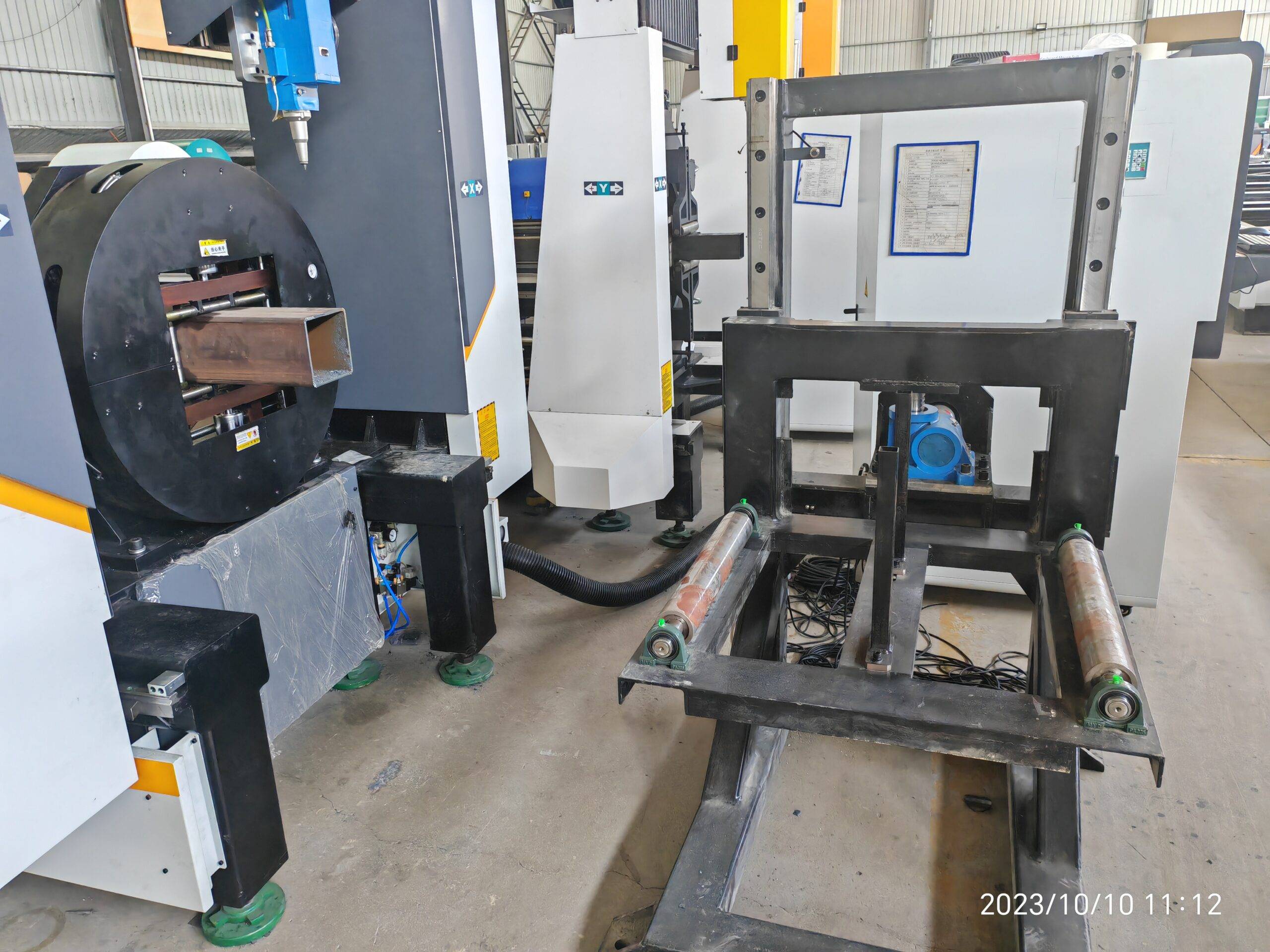
Technical Evaluation of Heavy-Duty CNC Pipe Laser Processing Centers for Modern Stadium Structural Frameworks
When specifying fabrication equipment for large-span stadium roof trusses and column structures, the primary challenge is no longer raw cutting speed. The bottleneck has shifted to material handling logistics and data integrity across the production chain. A heavy duty CNC pipe laser processing center for stadium construction must be evaluated not merely as a cutting tool, but as a synchronous node within a fully automated upstream/downstream workflow. In this analysis, we dissect the mechanical and control system requirements for handling 12-meter, 600mm diameter S355JR tubes with 20mm wall thickness, focusing on the integration of auto-bundling loaders and MES/ERP feedback loops.
Upstream/Downstream Automation Interfacing: The Real Throughput Killer
Stadium projects demand 8,000 to 15,000 individual tubular nodes and bracing members, each with unique bevel angles and coping profiles. Conventional manual loading and unloading introduces a 40-60% idle time penalty on the laser resonator. To achieve a true “lights-out” operation, the pipe laser processing center must be specified with a servo-driven, multi-station auto-bundling loader. This is not a simple chain conveyor. The loader must perform a critical pre-feeding function: individual tube separation. When 12-meter S355JR pipes are delivered in bundles, they exhibit residual bending stress and ovality. The loader’s hydraulic lift arms must use a comb-type separator to prevent jamming, operating at a cycle time of under 45 seconds per tube.
Downstream, the cut part take-away system must interface with a sorting gantry. For stadium nodes, which often weigh over 500 kg, the unloading chuck must release the part onto a powered roller bed with a pneumatic lift table. The critical parameter here is the synchronization between the CNC controller (typically Siemens 840D sl or Fanuc 31i) and the PLC controlling the material handling. We require a Profinet or EtherCAT bus cycle time of 1ms to ensure the chuck does not release prematurely during the final cut-off sequence, which would cause the tube to drop and damage the laser optics.
Mechanical Rigidity and Chucking Dynamics
For heavy-wall pipes, the physics of rotation are unforgiving. At a spindle speed of 30 RPM for a 600mm diameter tube, the moment of inertia is substantial. The headstock and tailstock chucks must exert a clamping force regulated at 3.2 MPa pneumatic pressure, with an optional hydraulic boost to 5.0 MPa for high-torque cutting. If the chuck pressure fluctuates by even 0.1 MPa during the cutting of a high-strength S355JR profile, you will induce micro-vibrations that cause the laser head to produce a striated edge finish, failing the ISO 9013 quality standard for weld preparation.
The linear guide rails on the gantry axis must be rated for a dynamic load capacity of at least 80 kN. We specify preloaded roller guides, not ball bearings, to handle the reaction forces from the cutting gas jet. When cutting with Nitrogen at 1.5 MPa delivery pressure to achieve a dross-free edge on stainless steel (SUS304) nodes, the reaction force on the nozzle is significant. The Z-axis carriage must have a stiffness rating of 50 N/µm to prevent nozzle collision.
MES/ERP Integration and Data Traceability
The modern stadium construction site demands digital twin integration. The laser cutting center must be equipped with an OPC UA server to push real-time production data to the MES. This is not just for monitoring. The system must automatically pull cutting programs from the ERP based on the bundle ID scanned by the loader. Each tube section is tracked via a unique Data Matrix code, which is engraved by the laser itself (at 20W fiber power, 50kHz frequency) on the tube end. This code ties the physical part to the 3D BIM model, allowing for automated robotic welding downstream.
We must also address the issue of remnant management. The CNC software must calculate the optimal nesting layout across multiple tube lengths to minimize waste. For a stadium project using Al6061-T6 for architectural fins, the remnant length must be tracked to the nearest 10mm. If the remnant is longer than 1.5 meters, the MES must automatically generate a new task to cut smaller bracing elements, ensuring a material utilization rate above 92%.
Comparative Analysis: Laser vs. Conventional Plasma/Sawing
To justify the capital expenditure, we must compare the operational efficiency against legacy methods. The table below outlines the critical metrics observed on recent stadium projects in the Middle East and Asia.
| Parameter | Conventional Plasma + Mechanical Saw | Heavy-Duty CNC Fiber Laser Center |
|---|---|---|
| Cutting Speed (10mm S355JR) | Plasma: 1.2 m/min (rough edge) | 4.5 m/min (laser, 12kW) |
| Bevel Angle Accuracy | ±2° (requires secondary machining) | ±0.3° (5-axis simultaneous control) |
| Kerf Width | 3.5 mm (material loss) | 0.8 mm (high-density cutting) |
| Heat Affected Zone (HAZ) | 1.5 mm (requires grinding) | 0.1 mm (ready for welding) |
| Setup Changeover Time | 25 minutes (manual tooling) | 4 minutes (automatic focus & chuck change) |
| Gas Consumption (N2) | N/A (uses compressed air) | 1.2 MPa at 200 L/min (optimized nozzle) |
| Operator Intervention | 1 operator per 2 machines (constant slag removal) | 1 operator per 4 machines (supervisory role) |
| Part Distortion | High (thermal stress) | Negligible (low heat input) |
The data is clear. The laser center reduces secondary operations by 70% and eliminates the need for separate chamfering machines. The integration of the auto-bundling loader ensures that the laser source is cutting for 85% of the shift duration, compared to 45% for manual-fed plasma systems.
Gas Delivery and Process Stability
For stadium structural steel (S355JR), we typically cut with Oxygen at 0.8 MPa to 1.2 MPa to achieve a clean oxide-free edge for painting. However, for the critical load-bearing nodes where fatigue resistance is paramount, we switch to Nitrogen at 1.5 MPa to prevent any oxidation. The gas delivery system must include a pressure regulator with a response time of less than 50ms to handle the sudden pressure drops when the laser pierces the 20mm wall thickness. A buffer tank of at least 500 liters must be installed near the cutting head to prevent pressure starvation during the piercing phase.
FAQ: Procurement Considerations for Stadium Projects
Q1: What is the minimum laser power required to cut 25mm thick S355JR pipe for stadium columns, and how does this affect the cooling system requirements?
For production reliability, we recommend a 12kW to 15kW fiber laser source. This allows cutting speeds of 1.8 m/min on 25mm wall thickness with Oxygen assist. The cooling system must be a closed-loop chiller with a cooling capacity of at least 60 kW, maintaining the resonator temperature at 22°C ± 1°C. Failure to manage the thermal load will result in power derating and inconsistent cut quality.
Q2: How does the auto-bundling loader handle the ovality and bending tolerances of standard ASTM A500 or EN 10210 tubes?
The loader must be equipped with a pre-straightening roller station. This station applies a controlled bending moment to reduce the tube’s ovality to less than 1% of the diameter before it enters the chuck. The CNC control must also run a “touch probe” cycle to map the actual tube surface profile before cutting, adjusting the focal point position dynamically to compensate for any residual deviation.
Q3: Can the MES integration track the thermal cutting history for weld traceability documentation required by ISO 3834?
Yes. The system logs every parameter: laser power, feed rate, gas pressure, and focal position, timestamped and linked to the part’s Data Matrix code. This data is exported in a CSV or XML format compatible with most quality management systems. This provides complete traceability from the steel mill certificate to the final welded joint, a mandatory requirement for public infrastructure projects.













