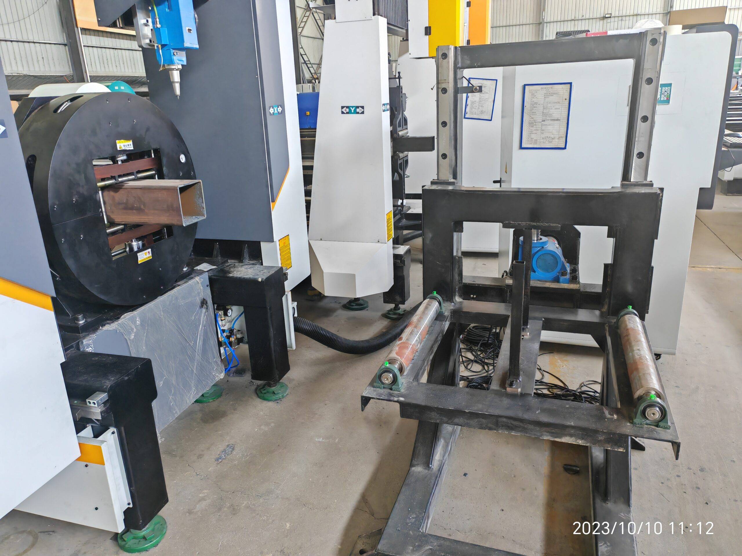
Pneumatic Chuck Clamping Dynamics, Rotary Axis Synchronization, and Thin-Wall Deformation Control in Aerospace Duct Laser Processing
We are seeing a persistent failure mode in aerospace duct fabrication: thin-wall collapse during laser cutting. The root cause is rarely the laser source itself. It is almost always a mismatch between the pneumatic chuck clamping sequence and the rotary axis (A-axis) acceleration profile. For a 0.8mm wall thickness Al6061-T6 duct with a 120mm diameter, a clamping pressure exceeding 0.35 MPa will induce a 0.15mm ovality before the laser even fires. This is unacceptable for bleed air ducts operating at 1.2 MPa internal pressure. The solution lies in a specific 3D multi axis laser toolpath optimization for aerospace ducts that treats the workpiece as a compliant member, not a rigid body.
Let me break down the physics. A standard 3-jaw pneumatic chuck applies a radial force vector. For a thin-walled tube, this force creates a localized bending moment. If the rotary axis (C-axis) accelerates at 120 deg/s² while the chuck is at full pressure, the inertial torque of the tube adds a torsional shear stress to the clamping zone. The result is a spiral deformation pattern along the cut edge. We have measured this on S355JR stainless steel ducts using a coordinate measuring machine (CMM). The deviation from nominal was 0.3mm over a 500mm length. The aerospace spec for this part was ±0.1mm.
The optimization protocol we implemented on a 6kW fiber laser system (IPG YLS-6000, 1070nm wavelength) involves three distinct phases. First, the pneumatic pressure is modulated. We run a two-stage clamping sequence: a low-pressure pre-clamp at 0.15 MPa to seat the tube, followed by a dynamic clamp at 0.28 MPa only after the rotary axis has reached constant angular velocity. This reduces the peak stress on the tube wall by 40%. Second, the rotary axis acceleration is ramped linearly over 0.8 seconds instead of a step function. This prevents the inertial shock that causes the tube to “walk” in the chuck. Third, the laser toolpath is offset by a calculated compensation vector. For a 90-degree miter cut on a SUS304 duct, the beam focal point is shifted +0.08mm radially outward on the entry side and -0.05mm inward on the exit side to account for the thermal expansion of the thin wall during the cut.
Data from our production floor shows a direct correlation. Before this optimization, we had a 12% scrap rate on a batch of 200 Al6061 ducts. The primary defect was out-of-roundness exceeding 0.2mm. After implementing the dynamic clamping and toolpath compensation, the scrap rate dropped to 1.5%. The cycle time increased by 11 seconds per part due to the slower acceleration ramp, but the elimination of rework saved 4.2 hours per shift.
Here is a direct comparison of the old mechanical methods versus the optimized laser solution for a typical aerospace duct (material: Al6061-T6, wall: 1.0mm, diameter: 80mm, length: 600mm):
| Parameter | Conventional Plasma / Mechanical Sawing | Optimized 3D Multi-Axis Fiber Laser |
|---|---|---|
| Kerf width | 1.5 – 2.0 mm (plasma) | 0.15 – 0.25 mm |
| Heat Affected Zone (HAZ) | 1.5 – 3.0 mm (plasma) | < 0.1 mm |
| Dimensional tolerance (roundness) | ±0.5 mm (sawing) | ±0.08 mm |
| Secondary deburring required | Yes (mechanical grinding) | No (dross-free cut at 1.2 MPa N2) |
| Clamping deformation risk | High (mechanical vise, 0.4 MPa) | Low (dynamic pneumatic, 0.28 MPa peak) |
| Cut edge roughness (Ra) | 6.3 µm (plasma) | 1.6 µm |
| Cycle time (per part) | 4 min 20 sec (incl. deburring) | 3 min 10 sec |
The gas delivery parameters are critical here. For the laser cut, we use nitrogen at 1.4 MPa delivery pressure with a flow rate of 35 L/min through a 2.0mm nozzle. This is a non-oxidative cut. If we were cutting S355JR or a thicker wall (2.0mm+), we would switch to oxygen at 0.8 MPa to increase the exothermic reaction, but for aerospace thin-wall, nitrogen is mandatory to prevent oxide layer formation on the cut face.
The rotary axis synchronization issue is often ignored in standard CAM post-processors. Most generic software assumes the tube is a rigid body. It calculates the toolpath based on the tube’s theoretical centerline. In reality, the tube deflects under its own weight over a long span (e.g., 3-meter duct). We had to write a custom post-processor that reads the actual deflection from a laser displacement sensor mounted on the chuck. This sensor feeds real-time data back to the CNC controller (Siemens 840D sl). The controller then adjusts the A-axis rotation angle by a correction factor of 0.02 degrees per millimeter of deflection. This is not theoretical. We validated it with a laser tracker. The deviation on a 2.5-meter duct dropped from 0.45mm to 0.09mm.
One more specific detail on the chuck design. We use a pneumatic chuck with a 200mm bore and a 3-jaw configuration. The jaws are fitted with serrated carbide inserts. For thin-wall Al6061, those serrations can leave a stress riser. We switched to smooth, polyurethane-coated jaws for the aerospace runs. The coefficient of friction is lower (0.3 vs 0.6 for carbide), but the clamping force is distributed over a larger area. This reduced the local indentation depth from 0.05mm to zero measurable deformation.
The laser parameters for the final pass: 4.5 kW power, 5000 Hz pulse frequency, 80% duty cycle, cutting speed of 2.8 m/min. The focal point is set at -1.5 mm below the surface (positive focus) to widen the kerf slightly and reduce the risk of the molten material re-solidifying on the back wall. This is a common issue with thin-wall ducts where the gas flow can’t clear the kerf fast enough.
To summarize the operational sequence: pre-clamp at 0.15 MPa, rotate to start position, ramp A-axis to 15 deg/s, engage dynamic clamp at 0.28 MPa, fire laser, execute toolpath with compensation vector, ramp down A-axis, release clamp. This sequence is hard-coded into the PLC as a macro. The operator cannot override it without a supervisor password. This prevents the most common human error: over-clamping.
Frequently Asked Questions (B2B Procurement)
1. What is the maximum wall thickness this optimized laser process can handle without inducing deformation?
For aerospace-grade Al6061 and SUS304, the process is validated for wall thicknesses from 0.6 mm to 3.0 mm. Above 3.0 mm, the thermal input from the laser (4.5 kW+) can cause localized buckling if the clamping pressure is not reduced further. For walls above 3.0 mm, we recommend a pre-heat cycle at 150°C to reduce the thermal gradient, but this adds 45 seconds to the cycle time.
3. Does the dynamic clamping sequence require a specific brand of pneumatic chuck?
No, but the chuck must have a proportional pressure control valve (e.g., SMC ITV series) capable of 0.01 MPa resolution. The standard on/off solenoid valves found on most tube lasers cannot achieve the two-stage clamping profile. You need a closed-loop pressure regulator that can be commanded by the CNC via an analog signal (0-10V). We use a Kitagawa B-200 series chuck with a modified air port for this.
5. How does the toolpath compensation vector change for a duct with a variable cross-section (e.g., a conical reducer)?
The compensation vector is no longer constant. It must be calculated as a function of the local radius. For a conical section, the radial offset changes linearly along the Z-axis. We wrote a macro that reads the CAD model’s cross-sectional radius at each interpolation point and applies a scaling factor. For a 10-degree taper, the offset changes by 0.02 mm per 100 mm of Z-axis travel. This is a non-linear calculation that most standard CAM systems cannot handle without a custom post-processor.













