Process Inefficiency in Structural Tube Fabrication: The Grinding Bottleneck
On any given H-beam or structural tube line, secondary grinding is not a value-add operation; it is a tax on prior process errors. When you are dealing with S355JR or S275JR material for EN 1090-2 execution classes, the weld seam preparation and profile cutting tolerances dictate whether your fitters are spending 15 minutes per joint with an angle grinder or 2 minutes with a flap disc. The physical reality is that conventional thermal cutting—plasma or oxy-fuel—introduces a heat-affected zone (HAZ) that hardens the edge to approximately 350-400 HB on structural steel. That hardened dross and oxide layer destroys abrasive consumables and eats man-hours. The shift toward fiber laser tube processing is not about speed alone; it is about eliminating the metallurgical need for grinding. If you are evaluating how to reduce secondary grinding on H beam and structural tubes, the answer lies in the physics of the cut edge and the repeatability of the clamping system, not in better abrasive wheels.
Metallurgical Root Cause: Why Plasma and Sawing Demand Secondary Finishing
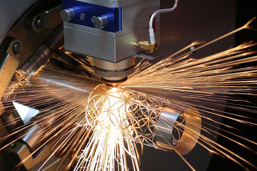
Let us break down the failure modes of legacy processes against the EN 1090 standard. With plasma cutting at 60-80 amps on a 12 mm flange, you are depositing roughly 1.2 to 1.8 kW of thermal energy into a localized zone. This creates a recast layer that is martensitic in nature. When you attempt to weld that edge without removal, you risk hydrogen-induced cold cracking, especially in thicker sections above 20 mm. Consequently, EN 1090-2 mandates that cut surfaces intended for butt welds must be free of scale and coarse ripples. That mandate forces the grinding operation. Mechanically sawed tubes, on the other hand, produce a burr and a work-hardened edge that requires deburring—a separate labor cell. The laser, specifically a 6 kW to 8 kW fiber source operating at a wavelength of 1064 nm, cuts by vaporization and melt shearing with a Nitrogen assist gas at 1.2 to 1.5 MPa. The resulting kerf width is 0.3 mm to 0.8 mm, versus 3.0 mm to 5.0 mm for plasma. The HAZ depth is reduced to below 0.1 mm, which is metallurgically negligible and does not require dressing prior to welding.
Chuck Pressure and Beam Stability: The Hidden Variables in Cut Quality
You cannot discuss grinding reduction without addressing the mechanical fixturing. On an H-beam, the web and flange thicknesses vary, often between 6 mm and 25 mm. If your laser tube cutting machine uses a standard 3-jaw chuck at a pneumatic pressure of 0.4 MPa, you will induce ovality on thin-walled sections. That ovality causes the focus position to shift by ±0.5 mm, which directly increases the striation depth on the cut face. Striations are a primary driver for secondary grinding because they act as stress risers. The correct approach is a self-centering chuck system with variable pressure control—ramping down to 0.2 MPa for thin walls and up to 0.8 MPa for heavy sections. Additionally, the use of a front and rear support steady rest, spaced at a maximum of 1/4 of the tube length, eliminates vibration-induced chatter. A stable cut with a Ra roughness of 3.2 µm or better on the cut edge is the threshold where grinding becomes optional, not mandatory.
Comparative Process Data: Laser vs. Conventional Methods
To quantify the operational shift, review the following comparative metrics observed on a production floor processing 150 mm x 150 mm x 10 mm structural tubes (S355JR) for a modular steel frame project:
| Parameter | Conventional Plasma (120A) | Mechanical Saw (Cold Cut) | Fiber Laser (8kW, N₂ Assist) |
|---|---|---|---|
| Cutting Speed (m/min) | 0.8 – 1.2 | 0.3 – 0.5 | 3.5 – 4.5 |
| Kerf Width (mm) | 3.5 – 5.0 | 2.0 – 3.0 | 0.4 – 0.8 |
| HAZ Depth (mm) | 1.5 – 2.5 | 0.5 (mechanical deformation) | < 0.1 |
| Edge Roughness (Ra µm) | 12 – 25 | 6 – 10 | 2 – 4 |
| Secondary Grinding Time (min/joint) | 12 – 18 | 8 – 12 (deburring) | 0 – 2 (cosmetic only) |
| Dross Condition | Heavy, adhered oxide | Burr, mechanical lip | None (clean, oxide-free) |
| EN 1090-2 Compliance | Requires full dressing | Requires deburring | Directly weldable |
The data indicates a reduction in post-processing labor of approximately 85% to 90%. However, the critical metric for certification readiness is the consistency of the cut. A laser maintains a standard deviation of ±0.05 mm on cut length, whereas plasma varies by ±1.5 mm. That variance is what causes fit-up gaps, which welders compensate for by adding filler material, which then requires grinding. Eliminate the gap, and you eliminate the grind.
Gas Selection and Duty Cycle: Optimizing for Aluminum and Stainless
For fabricators handling mixed materials—say SUS304 stainless steel handrails or Al6061 architectural members—the gas selection protocol changes the grinding equation. On stainless, using Oxygen at 0.8 MPa creates a heavy oxide layer on the cut face that is notoriously difficult to remove. Switching to Nitrogen at 1.5 MPa yields a bright, silver-colored edge that is oxidation-free. For Al6061, the laser pulse frequency must be increased to 5 kHz with a duty cycle of 60% to prevent the formation of a burr on the bottom edge. A burr on aluminum is a safety hazard and a grinding necessity. By tuning the pulse width modulation, you achieve a burr-free edge, eliminating the secondary operation entirely. This is not theoretical; it is a matter of setting the correct focal position (typically -2 mm below the surface) and maintaining a nozzle standoff of 0.8 mm.
Operational Workflow for Certification Readiness
To achieve EN 1090 certification without the grinding bottleneck, your workflow must be restructured around the laser’s capabilities. First, implement a nesting algorithm that prioritizes common-line cutting to reduce the number of individual profiles. Second, utilize the laser’s ability to cut bevels (up to 45 degrees) directly on the tube end. This pre-beveling eliminates the need for edge preparation in the fit-up stage, which is a major source of grinder usage. Third, integrate a vision system or mechanical probing to measure the actual tube dimensions before cutting. H-beams from the mill often have a web height tolerance of ±2 mm. If the laser program does not compensate for this, the weld gap will be inconsistent. By probing and adjusting the program in real-time, you maintain a gap of 1.5 mm ± 0.5 mm, which is the sweet spot for a single-pass fillet weld without backing grind.
The financial impact is substantial. If you are paying a certified welder $35/hour to grind instead of weld, and they spend 20% of their shift on grinding, that is a direct loss of $14,000 per welder per year. With a laser system, that welder’s arc-on time increases from 35% to 65%. The return on investment is calculated not on cutting speed, but on the reduction of non-value-added labor and the elimination of abrasive consumable costs (which can run $2,500 to $4,000 per month on a high-volume plasma line).
FAQ: Procurement Considerations for Laser Tube Systems
Q1: Can a fiber laser effectively cut H-beam profiles with varying flange thickness without excessive burr on the bottom edge?
Yes, but only with a system that has a B-axis (tilt) capability and a high-pressure Nitrogen supply (up to 2.0 MPa). The key is to use a dynamic focus control that adjusts the focal position based on the material thickness profile. For an H-beam, you cut the web first, then the flanges, using a piercing delay of 200 ms to avoid slag adhesion on the lower flange. Burr formation is minimized by maintaining a cutting speed above 3 m/min to ensure the melt is ejected before it re-solidifies.
Q2: What is the specific power requirement to cut S355JR up to 25 mm thick for structural applications?
You need a minimum of 6 kW for reliable cutting up to 20 mm, but for 25 mm thick flanges, an 8 kW source is recommended. The cutting gas pressure should be set to 1.2 MPa for Nitrogen. At this power level, you will achieve a cut speed of 1.8 m/min on 25 mm thickness. Below 6 kW, you risk incomplete penetration and a heavy dross that requires grinding, which defeats the purpose.
Q3: How does the laser cutting process affect the mechanical properties of the HAZ concerning EN 1090-2 Charpy impact tests?
The laser’s rapid cooling rate (approximately 10^4 °C/s) creates a fine-grained martensitic structure in the immediate 0.1 mm zone. However, because this zone is so thin, it does not significantly alter the overall Charpy V-notch impact values of the base material. In practice, test specimens cut by laser and then welded consistently achieve 27 J at -20°C, meeting the EN 1090-2 requirements for S355JR. The critical factor is to avoid using Oxygen as an assist gas, as it introduces carbon into the cut edge, embrittling it. Always use Nitrogen or Argon for structural certifications.













